
APEX ORIN NX II PPS Usage#
Notice
Use an additional serial port as the PPS UART interface.
The PPS interface converts the MiiVii device’s system time into a high-precision PPS output signal. This interface cannot be programmed. It is mainly used to synchronize the sensor system without a GPS device.
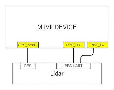
Hardware Definition#
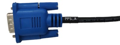
Pin Definition:
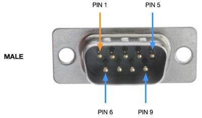
Pin |
Signal |
|---|---|
1 |
GND |
6 |
PPS_A_SYNC |
Pin |
Specification |
|---|---|
PPS_A_SYNC |
5V |
Usage#
Configure the Serial Port for GPRMC Output#
vim  /opt/miivii/config/sync/pps_out.cfg
Change the value after uart_dev: from NONE to /dev/ttyUART_232_A or /dev/ttyUART_232_B
Restart the device
Configure the GPRMC Serial Port Baud Rate#
Edit /etc/systemd/miivii-autostarter.sh
In the following line:
/usr/local/bin/pps_sync 9600 > /var/log/pps_sync.log &
9600 is the PPS serial baud rate.
refclock PPS /dev/pps0 lock GPSD prefer refid PPS 〉refclock PPS /dev/pps2 lock GPSD prefer refid PPS
PPS OUT Usage#
PPS OUT Specifications#
The default baud rate is 9600
PPS OUT Function#
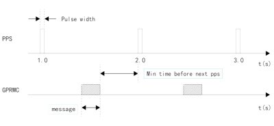
The device outputs a PPS signal(one pulse per second with a pulse width of 50ms) and sends an NMEA GPRMC message through the Tx pin of the serial port (UART/RS232), indicating the time of the pulse’s rising edge. Example message:
$GPRMC,060249.000,A,3949.63046,N,11616.48565,E,0.296,,291118,,,A*4d
“060249.000” is the UTC timestamp when the pulse is generated each second, in hhmmss.000 format. Normal timestamps are aligned to whole seconds. Sensors supporting PPS synchronization use the received PPS signal and GPRMC messages to calibrate their clocks to the device’s system clock. Each sensor’s sampling time is sent to the device as a timestamp together with its data. The system thereby obtains the sensor sampling time in its own time base and completes synchronization.
PPS Synchronization Diagram#
Synchronization Verification (RS-LiDAR-16 as an Example):
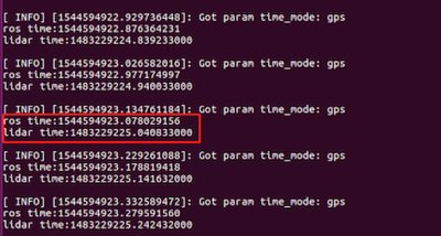
When only the sensor’s data interface is connected to the device, without connecting PPS_A_SYNC and PPS_A_TX, timestamps in the data uploaded by the sensor’s ROS node are hardware timestamps from the sensor’s internal clock counter. Most sensors use a fixed initial time and start counting at each power-on. Print these hardware timestamps in Ubuntu and compare them with the device’s system time; a large difference will be observed.
RS-LiDAR-16 Hardware Timestamp Compared with System Time before Synchronization#
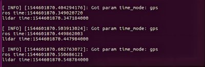
After the sensor is connected to PPS_A_SYNC and PPS_A_TX, hardware timestamps uploaded by its ROS node reflect the sensor clock synchronized by PPS and are consistent with the device’s system time. In Ubuntu, print the received hardware timestamp and compare it with the system time when the data is received (ros::time::now). A difference of less than 100ms indicates that PPS synchronization is working.
Data Timestamp Compared with System Time#
General Troubleshooting Guide for PPS Calibration Issues#
Symptom 1: “Connection Timed Out” Appears When Testing PPS with a Command Line Tool#
Solution:#
Check the Physical Connections
1) Ensure that the PPS signal cable is firmly connected to the designated interface and is not loose or connected to the wrong port.
2) Check the signal cable connector for visible oxidation, damage, or bent contacts.
3) Disconnect and reconnect the signal cable, then test whether the timeout still occurs.
4) If the signal source is an external device, such as a GPS module, use another known-good device to verify the signal output.
Verify the Signal Source
1) Enter the following command in a terminal to check the currently detected PPS source:
# Replace with the actual device node
sudo cat /dev/pps0
2) Normal output continuously displays timestamps and sequence numbers, for example:
source 0: 1715652256.000018408 sequence: 7929
3) If there is no output or an error occurs, check whether the signal source is operating normally.
Symptom 2: The System Does Not Recognize the PPS Source#
Solution:#
Check the Driver
1) Enter the following command to verify whether the driver is loaded:
dmesg | grep -i "pps"
2) If the output contains “No PPS source found”, reinstall or update the PPS driver.
Reconfigure the Input Port
1) Edit the system configuration file and specify the correct PPS device node:
# Or the path of another configuration file
sudo vim /etc/pps.conf
2) Restart the service after making changes:
sudo systemctl restart pps.service
Symptom 3: The PPS Period Is Unstable or the Error Is Excessive#
Solution:#
Eliminate Environmental Interference
1) Check for strong electromagnetic interference near the device, such as high-power motors or high-frequency communication equipment.
2) Test the device in a shielded environment and check whether the signal becomes stable.
Calibrate the Local Clock
1) Enter the following command to synchronize the local clock with the PPS signal:
# Use a calibration tool to verify synchronization accuracy
sudo ppscheck -s /dev/pps0
2) If the reported deviation exceeds the threshold, such as ±1ms, check the signal cable length or use a high-quality shielded cable.
Technical Support#
If the issue persists after all the checks above, try the following:
Restore the system image: back up your data, flash the system image again, and reconfigure the PPS service.
If the issue persists, provide Technical Support with:
1) The signal source model and firmware version;
2) Screenshots showing the full terminal command output;
3) A record of configuration file changes.