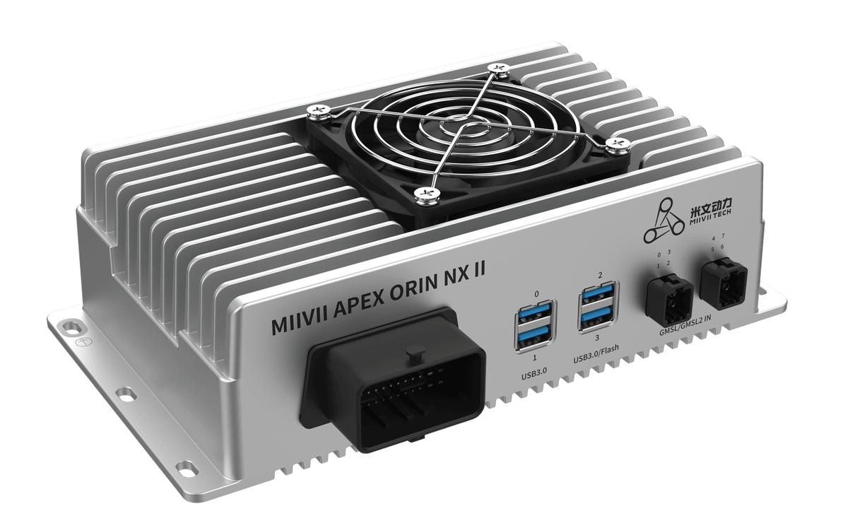
APEX ORIN NX II CAN Interface#
Hardware Specifications#
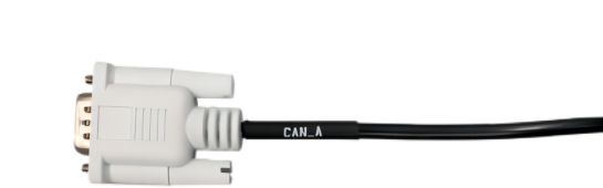
DB9 Pin Definition for the Isolated CAN Bus:
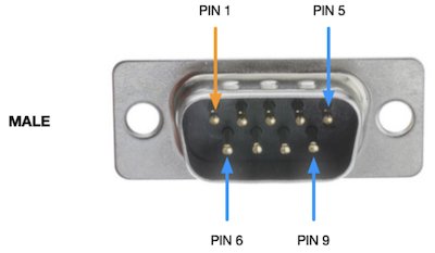
Pin Definition
Pin |
Signal |
|---|---|
2 |
CAN_L |
3 |
CAN_GND |
7 |
CAN_H |
Item |
Specification |
|---|---|
Isolation Voltage |
3000V |
Isolated Pins |
CAN_H, CAN_L, CAN_GND |
Relationship between Functions and Device Nodes#
Function |
Overview |
Device Node |
|---|---|---|
CAN_A |
CAN0 |
can0 |
CAN_B |
CAN1 |
can1 |
Usage#
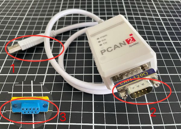
Connect connector 1 to the PC
Connect connector 2 to DB9 female-to-female crossover adapter 3
Connect connector 3 to the required DB9 CAN connector
Preparation#
Device
# Configure parameters (can0 is used as an example)
sudo ip link set can0 up type can bitrate 500000 dbitrate 5000000 sjw 4 restart-ms 1000 berr-reporting on fd on
PC
# Install
sudo apt-get install can-utils -y

# After connecting the USB-to-CAN (PCAN) device to the PC, run the following command to obtain the CAN interface name:
ls /sys/class/net/ | grep -E 'can[0-9]+' | sort -V | tail -n 1

# Configure
sudo ip link set can0 up type can bitrate 500000 sjw 4
Transmit and Receive Verification#
Device Sends Data, PC Receives#
Device
# Run the command to send data
sudo cansend can0 123#abcdabcd
PC
# Run the command on the PC to receive data
sudo candump can0
# The following output indicates that the device sent the data successfully
can0  123   [4]  AB CD AB CD
PC Sends Data, Device Receives#
PC
# Run the command to send data
sudo cansend can0 123#abcdabcd
Device side
# Run the command to receive data
sudo candump can0
# Check the device terminal. The following output indicates that the device sent the data successfully
can0  123   [4]  AB CD AB CD
Troubleshooting#
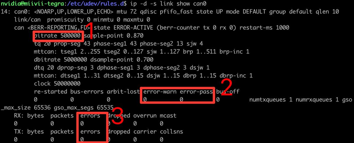
If no data is received, packets are lost, or communication errors occur,
use the following command to view the status of can0
ip -d -s link show can0

# Check whether 1 matches the previously configured value.
# Check whether 2 and 3 are both 0.
# If 1, 2, and 3 are normal, check the hardware connections.
# If an issue remains and its cause cannot be identified, contact Technical Support.
Reference#
Isolated CAN Description#
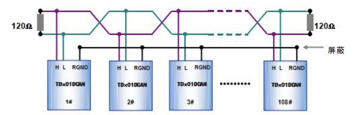
Although the CAN bus transmits differential signals and the receiver detects the voltage difference between the two lines, the common-mode voltage must remain within the CAN interface module’s allowable range for the network to operate normally. Exceeding this range can reduce communication stability and reliability or damage the interface. Isolation helps address common-mode noise. TD CAN series isolated CAN transceivers isolate ground loops between bus nodes and reduce ground-loop current, thereby reducing common-mode interference. In environments with severe interference or harsh electrical conditions, shielded twisted-pair cable is still recommended. Connect the bus reference grounds of the communication nodes through the shield to reduce conducted and radiated common-mode interference and improve communication reliability.
CAN Troubleshooting#
Symptom 1: CAN Communication Fails after the Device Starts#
Check 1: Check the Hardware#
Step 1: Check the Interface for Damage#
If the interface is visibly damaged, contact MiiVii After-Sales Support.
If there is no damage, proceed to “Step 2: Cross-Check”.
Step 2: Cross-Check (If Another Device Is Available)#
Connect the cable and the peripheral transmitting CAN data to another device and check communication.
If another device communicates normally with the same configuration, the issue is likely specific to this device’s hardware. Contact MiiVii After-Sales Support.
If the other device also fails to communicate, check the cable and CAN peripheral for faults.
If another device is unavailable, connect two CAN ports on the device together and proceed to “Step 3: Connect Two Ports to Verify Operation”.
Step 3: Connect Two Ports to Verify Operation#
Use jumper wires to connect the affected CAN port to another CAN port, then verify transmission and reception with cansend and candump. For CAN pin definitions and transmit/receive verification, see: https://wiki.miivii.com/pages/viewpage.action?pageId=182034048.
If the two CAN ports communicate normally, check the cable and CAN peripheral for faults.
If the two CAN ports cannot communicate, proceed to “Check 2: Check the CAN Configuration”.
Check 2: Check the CAN Configuration#
Step 1: Use ifconfig -a to check the interface status#
Open a terminal and enter:
ifconfig -a
If the affected CAN interface is missing, proceed to “Step 2: Check CAN Initialization (NV mttcan Is Not Loaded by Default)”.
If the affected CAN device node is listed, proceed to “Step 3: Configure CAN Parameters”.
Step 2: Check CAN Initialization (NV mttcan Is Not Loaded by Default)#
Load the CAN device node:
sudo modprobe can
sudo modprobe can_raw
sudo modprobe mttcan
After reconfiguring the CAN device node, use ifconfig -a to verify whether it is listed.
If the CAN device node is listed, proceed to “Step 3”.
If the CAN device node is not listed, the issue is likely specific to the device’s hardware. Contact MiiVii After-Sales Support.
Step 3: Configure CAN Parameters#
Enter:
sudo ip link set can2 up type can bitrate 500000 dbitrate 5000000 restart-ms 1000 berr-reporting on fd on
These parameters configure the CAN interface bit rates: 500K is used for CAN 2.0 transmission, and 5M is used for CAN FD transmission.
Note: The CAN interface bit rate must match the bit rate of the peripheral transmitting CAN data
If CAN communication works after reconfiguration, the issue is resolved.
If CAN communication still fails after reconfiguration, proceed to “Check 3: Flash the Image Again to Check for a Software Environment Issue”.
Check 3: Flash the Image Again to Check for a Software Environment Issue#
Step 1: Flash the Image#
For image flashing instructions, see: https://wiki.miivii.com/pages/viewpage.action?pageId=182034027.
After flashing the image, configure the CAN device node again and verify CAN communication.
If CAN communication works after flashing, the issue was caused by the system software environment. Investigate your software environment.
If communication still fails after flashing, connect the device to the Internet and proceed to “Step 2: Collect Logs”.
Step 2: Collect Logs#
Connect the device to the Internet, open a terminal, and enter:
curl -sSL https://doc.miivii.com/scripts/run_miivii_diagnostic.sh | bash -s can
Export the logs and upload them to the support ticket system for analysis by MiiVii after-sales engineers.
Symptom 2: CAN Communication Becomes Blocked after Running for a Period of Time#
Check 1: Check the External Environment#
Check 2: Check the CAN txqueuelen Configuration#
Step 1: Check the txqueuelen Value#
Open a terminal and enter:
sudo ip link show can0 | grep txqueuelen
Step 2: Set txqueuelen to a Maximum of 65536#
Open a terminal and enter:
sudo ip link set can0 txqueuelen 6553
If CAN communication works after this change, adjust the value to suit your requirements.
If CAN communication remains blocked, reproduce the issue, connect the device to the Internet, open a terminal, and enter: curl -sSL https://doc.miivii.com/scripts/run_miivii_diagnostic.sh | bash -s can. Export the logs and upload them to the support ticket system for analysis by MiiVii after-sales engineers.