APEX AD10 DO Usage#
Hardware Specification#
Electrical Characteristics#
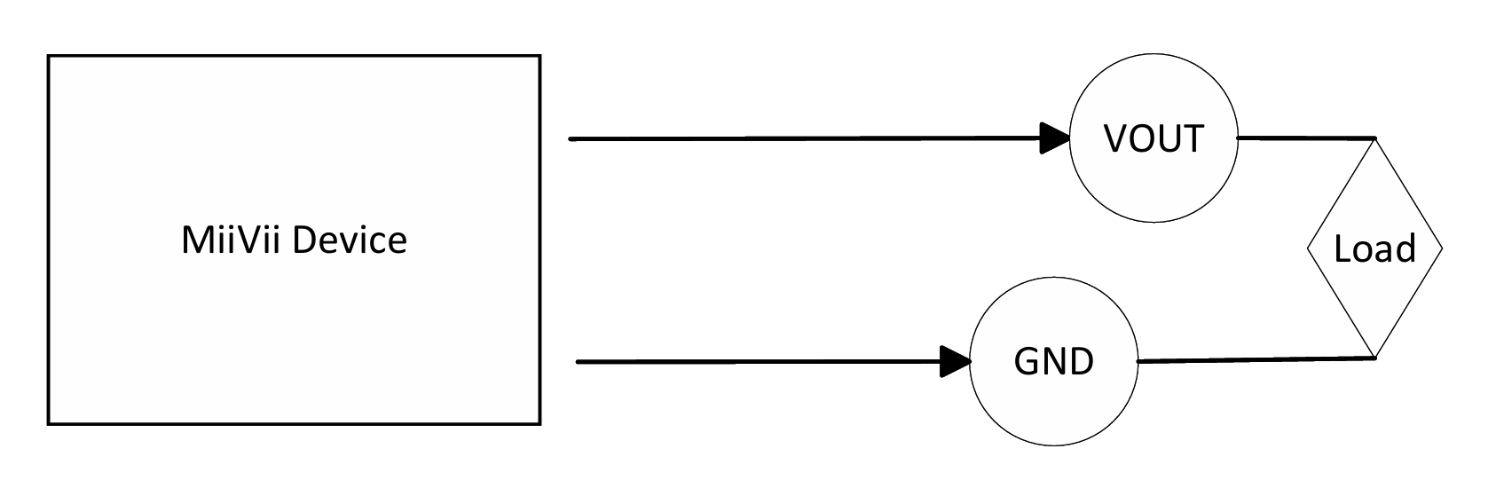
Description |
|
|---|---|
Vout |
Output voltage |
GND |
Ground |
Load |
Load |
Vout Result |
|
|---|---|
high level=1 |
3.3V |
low level=0 |
0V |
Pin Definition#
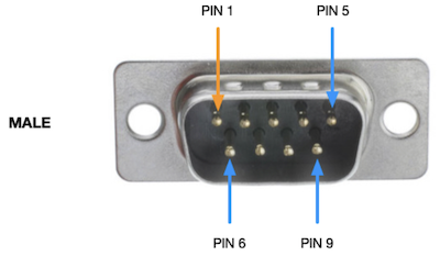
Function |
DB9 PIN Number |
Description |
Device Node |
|---|---|---|---|
DI_0 |
1 |
GPIO IN |
/dev/gpio/di0 |
DI_1 |
2 |
GPIO IN |
/dev/gpio/di1 |
DO_0 |
3 |
GPIO OUT |
/dev/gpio/do0 |
DO_1 |
4 |
GPIO OUT |
/dev/gpio/do1 |
DO_2 |
5 |
GPIO OUT |
/dev/gpio/do2 |
GND |
6-9 |
Ground |
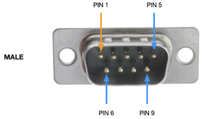
Function |
DB9 PIN Number |
Description |
Device Node |
|---|---|---|---|
DO_3 |
1 |
GPIO OUT |
/dev/gpio/do3 |
DI_2 |
3 |
GPIO IN |
/dev/gpio/di3 |
DI_3 |
5 |
GPIO IN |
/dev/gpio/di2 |
GND |
6/8 |
Ground |
Method of Application#
System version below 5.x.x-x.x.x#
The example of using the GPIO interface is as follows.
# Use root
sudo su -

# Set output to high
echo 1 > /sys/class/gpio/<device node>/value
# Example: echo 1 > /sys/class/gpio/gpio339/value

# Set output to low
echo 0 > /sys/class/gpio/<device node>/value
# Example: echo 0 > /sys/class/gpio/gpio339/value
System version above 6.x.x-x.x.x#
The usage of GPIO is as below
sudo /opt/miivii/features/gpio/bin/miivii_set_do_level <DO number> <level: 0/1> <duration(seconds) of level>
#<DO number>: Represents the sequence number of the DO. 0 represents DO1, 1 represents DO1, and so on.
#<level: 0/1>: Represents the level to be set. 0 represents low level, and 1 represents high level.
#<duration(seconds) of level>: The duration of the level in seconds. During this period, the DO level will be in the state specified by <level: 0/1>. After the level duration is exceeded, the DO returns to its previous state.

#Please note that starting from Linux kernel version 4.8, the GPIO SYSFS interface is marked as deprecated and is no longer supported in Jetpack 6.0 and later versions. It is recommended to use libgpiod for GPIO operations. Therefore, setting the level without specifying a duration is not supported.
#Example: Set DO0 to high level with a duration of 20 seconds.
#sudo /opt/miivii/features/gpio/bin/miivii_set_do_level 0 1 20
Compile sample code
cp -r /opt/miivii/features ~/
cd ~/features/gpio
sudo make;
Troubleshooting of GPIO issues#
Phenomenon: The serial port cannot communicate after the device is powered on. Solution:#
I. Hardware environment inspection operation steps:#
Check the physical interface status:
1) Observe whether there is physical damage such as deformation, breakage, or oxidation on the serial port interface.
2) If damage is found: Contact the device manufacturer’s after-sales service.
Cross-validation test:
Method 1: Connect the serial cable and peripheral device to another normal device and test whether communication is possible:
1) If the other device is normal → The current device has a hardware failure and after-sales service needs to be contacted;
2) If the other device is abnormal → Check whether the cable or peripheral device is damaged.
Method 2 (when there is no other device): Use a test cable to short-circuit two serial ports of the current device (for example, serial port A and serial port B), and test self-transmission and self-reception through a serial port debugging tool:
1) If the transmission and reception are normal → The original peripheral device or cable is faulty;
2) If the transmission and reception fail → The device hardware or system is abnormal.
Short-circuit test:
1) Use a Dupont wire to short-circuit the faulty serial port and other serial ports, and use a serial port debugging tool to verify transmission and reception (Refer to the user manual for the pin definitions of RS232/485/422 and the transmission and reception verification methods).
2) If the two serial ports can communicate normally, it is recommended to check whether there is a fault in the cable and the serial port peripheral device.
3) If the two serial ports cannot communicate normally, execute “Investigation item: Check whether the serial port is correctly configured”.
II. Serial port configuration inspection operation steps:#
1.** **View the current serial port configuration: Enter the command in the terminal (adjust according to the actual serial port node, such as /dev/ttyS0):
# View parameters such as baud rate
stty -F /dev/ttyS0 -a
Key parameters: The baud rate must be exactly the same as that of the peripheral device (such as 115200, 9600, etc.).
2、Fix configuration issues:
If the baud rate is inconsistent: Modify the serial port configuration to match the peripheral device (administrator privileges are required):
# Example: Set the baud rate to 115200
stty -F /dev/ttyS0 115200
If the failure persists even with consistent configurations: Proceed to the system image verification and troubleshooting.
III. Operation steps for system image verification:#
Re - flash the system image: Obtain the latest system image file from the device manufacturer and complete the flashing (backup data before operation).
Verification after flashing: 1) If communication is restored → The original system software environment is abnormal, and you need to check the configuration by yourself. 2) If it is still abnormal → Run the diagnostic script and submit the log:
# RS232串口诊断(示例)
curl -sSL https://support.example.com/diagnose_rs232.sh | sh
# RS485/422串口诊断(示例)
curl -sSL https://support.example.com/diagnose_rs485.sh | sh