APEX THOR PPS Usage#
Hardware Specification#
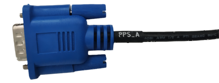 PPS DB9 Port Pin Definition:
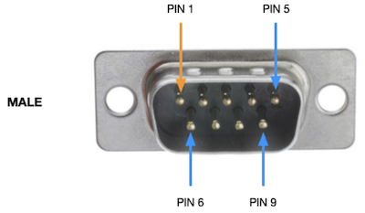
Pin |
Signal |
|---|---|
1 |
GND |
2 |
PPS_A_RX |
3 |
PPS_A_TX |
5 |
GND |
6 |
PPS_A_SYNC |
Pin |
Specification |
|---|---|
PPS_SYNC |
3.3V |
UART |
RS232 |
PPS Usage#
The PPS interface means that the MiVin device converts its own system time into a high-precision PPS signal and outputs it externally. This interface cannot be programmed, and is mainly used to achieve synchronization of the entire sensor system without the GPS device.
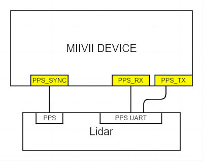
PPS OUT Function#
The device outputs a PPS signal (generating one pulse per second with a pulse width of 50ms) and transmits the NMEA GPRMC message through the Tx pin of the serial port (UART/RS232) indicating the time of the rising edge of the pulse. Here is an example of the message:
$GPRMC,060249.000,A,3949.63046,N,11616.48565,E,0.296,,291118,,,A*4dv
The timestamp “060249.000” represents the time in UTC when each pulse is generated per second. The format is in “hours:minutes:seconds.000”, with normal time being in whole seconds format. Sensors that support PPS synchronization mode will use the received PPS and GPRMC messages to calibrate their clock systems, keeping them in sync with the device’s system clock. The sampling time of the sensor will be taken as a timestamp and sent to the device together with the data. At this point, the system acquires the system time of the sensor’s sampling and completes synchronization.
PPS Synchronization Schematic Diagram

Verification method for synchronization function (taking RS-LiDAR-16 LiDAR as an example):
When the sensor is only connected to the device via the data input interface, without connecting to the PPS_A_SYNC port and PPS_A_TX of the device, the timestamp in the data uploaded by the sensor’s ROS node to the operating system is the hardware timestamp, which represents the time of the sensor’s internal clock counter (most sensors set a fixed initial time as the starting point for timing, starting counting after each power-up). At this point, printing the hardware timestamp in the Ubuntu operating system and comparing it with the device’s system time will reveal a significant deviation between the two.
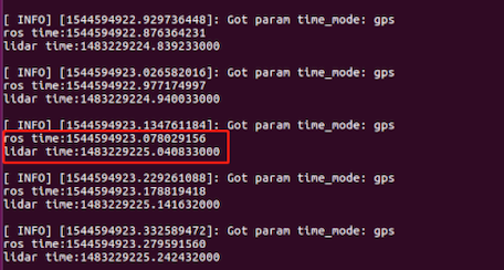
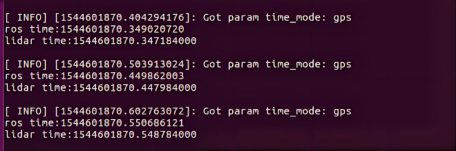
When the sensor is connected to the PPS_A_SYNC and PPS_A_TX of the device, the hardware timestamp in the data uploaded by the sensor’s ROS node to the operating system is the time of the sensor’s internal clock after being synchronized by PPS, which is consistent with the device’s system time. At this point, printing the received hardware timestamp in the Ubuntu operating system and comparing it with the system time at the time of receiving the data (ros::time::now), if the difference between the two is less than 100ms, it indicates that the PPS function is effective.
Comparison between data timestamp and system time.
Usage#
Modification method#
Support serial port baud rate
Baud rate |
|---|
9600 |
57600 |
115200 |
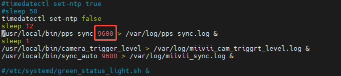
# Edit the following file to modify the GPRMC serial port /etc/systemd/miivii-autostarter.sh
# Replace 9600 with the target baud rate you want to change to
# Use the following command to make the modification take effect
sudo systemctl restart miivii-autostarter.service
Verification method#
Use the following tools to modify the serial port baud rate. If you see the following output, it means the modification was successful.
$GPRMC,060249.000,A,3949.63046,N,11616.48565,E,0.296,,291118,,,A*4d
Usage method of serial port tool
Preparation#
PC(Ubuntu System)
#Install
sudo apt-get install putty -y
Device
#install
sudo apt-get install putty -y
Receive-Send Test#
Device
#Open putty
sudo putty
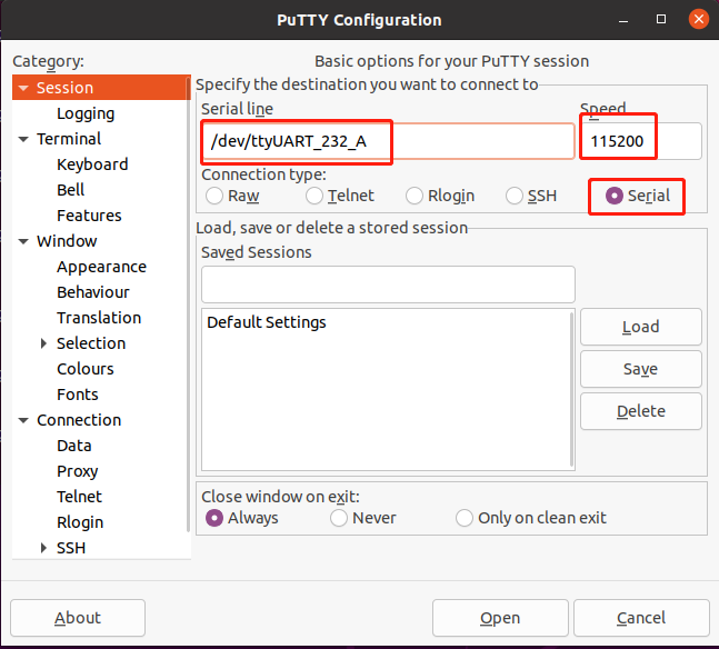
After opening Putty, configure the parameters in “Session”. Enter the device node in “Serial line” and set the speed to 115200 in “Speed”. Choose “Serial” in “Connection type”.
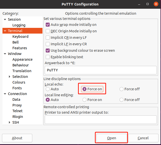
Configure the parameters in “Terminal”, select “Force on” in “Line discipline options”, and then click “Open” to enter the data transfer interface.
PC
Obtaining the UART device node on the PC side.
#After connecting the USB to serial module to the PC side, execute the command, and the output result is the UART device node.
 ls /dev | grep -E 'ttyUSB[0-9]+' | sort -V | tail -n 1

#Open putty
sudo putty
After opening Putty, configure the parameters in “Session”. Enter the device node in “Serial line” and set the speed to 115200 in “Speed”. Choose “Serial” in “Connection type”.
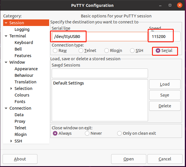
Configure the parameters in “Terminal”, select “Force on” in “Line discipline options”, and then click “Open” to enter the data transfer interface.
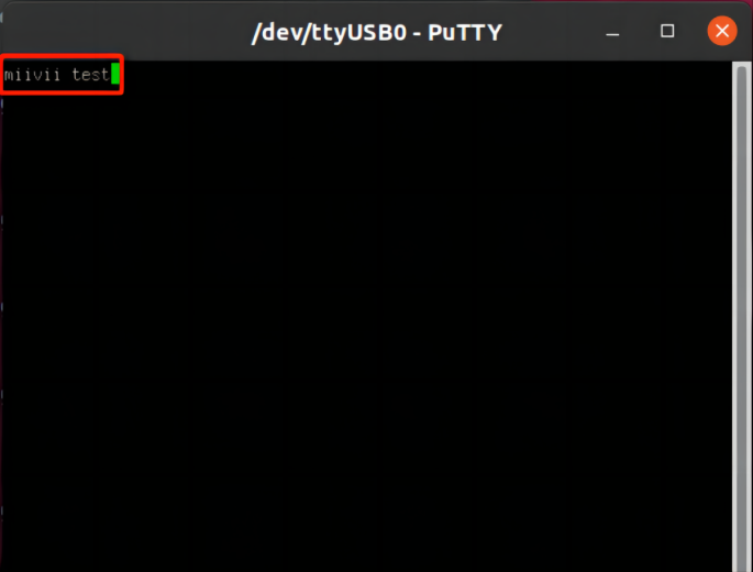
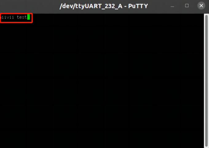
Use PuTTY to determine whether the send and receive operations are successful.
Observe the transmission interfaces on both the device side and the PC side. Enter any information in either interface, and if both interfaces display the same content, it means that the send and receive operations are successful.
PC
Device
General Troubleshooting Guide for Abnormal PPS Signal Calibration of Devices#
Phenomenon 1: When testing the PPS signal using the command - line tool, it prompts “connection timeout”.#
Solution:#
1、Check the physical connections of the hardware
1) Confirm that the PPS signal cable is firmly inserted into the designated interface of the device to avoid looseness or incorrect insertion. 2) Check whether there is obvious oxidation, damage or bending at the signal cable interface. 3) It is recommended to unplug and replug the signal cable once, and then test whether the timeout prompt still appears. 4) If the signal source is an external device (such as a GPS module), try replacing it with another normal device to verify the signal output.
Verify the status of the signal source 1) Enter a command in the terminal to view the currently recognized PPS signal source:
# Replace with the actual device node
sudo cat /dev/pps0
2) Normal output: Continuously display the timestamp and serial number (example):
source 0: 1715652256.000018408 sequence: 7929
3) No output or error: Check if the signal source device is working properly.
Phenomenon 2: The system cannot recognize the PPS signal source#
Solution:#
1、Check the installation status of the driver
1)Enter the command to verify whether the driver is loaded:
dmesg | grep -i "pps"
2)If the output contains “No PPS source found” → reinstall or update the PPS driver.
2、Reconfigure the input port
1)Edit the system configuration file and specify the correct PPS device node:
# Or the path of other configuration files
sudo vim /etc/pps.conf
2)Restart the service after modification:
sudo systemctl restart pps.service
Phenomenon 3: The PPS signal period is unstable or has an excessive error#
Solution:#
1. Eliminate environmental interference 1) Check whether there are strong electromagnetic interference sources (such as high - power motors, high - frequency communication equipment) around the device. 2) Move the device to a shielded environment for testing and observe whether the signal returns to stable. 2. Calibrate the local clock 1) Enter the command to synchronize the local clock with the PPS signal:
# 使用校准工具验证同步精度
sudo ppscheck -s /dev/pps0
2)If the output display deviation exceeds the threshold (such as ±1ms), the length of the signal cable needs to be checked or a high-quality shielded cable should be replaced.
Technical support#
If the problem is not resolved after checking all the steps above, you can try the following operations:
1. System image repair: Re - burn the system image (backup data before operation), and re - configure the PPS service after completion. 2. If the problem persists, submit the following information to technical support: 1) Signal source device model and firmware version; 2) Screenshot of the complete output of the terminal command; 3) Configuration file modification record.