APEX THOR DI Usage#
Hardware Specification#
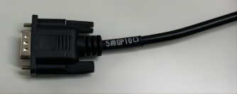
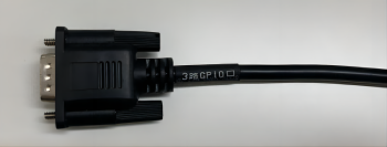
Pin Definition#
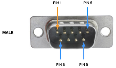
Function |
DB9 PIN Number |
Description |
Device Node |
|---|---|---|---|
DI_0 |
1 |
GPIO IN |
/dev/gpio/di0 |
DI_1 |
2 |
GPIO IN |
/dev/gpio/di1 |
DO_0 |
3 |
GPIO OUT |
/dev/gpio/do0 |
DO_1 |
4 |
GPIO OUT |
/dev/gpio/do1 |
DO_2 |
5 |
GPIO OUT |
/dev/gpio/do2 |
GND |
6-9 |
Ground |
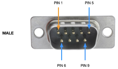
Function |
DB9 PIN Number |
Description |
Device Node |
|---|---|---|---|
DO_3 |
1 |
GPIO OUT |
/dev/gpio/do3 |
DI_2 |
3 |
GPIO IN |
/dev/gpio/di3 |
DI_3 |
5 |
GPIO IN |
/dev/gpio/di2 |
GND |
6/8 |
Ground |
Electrical Characteristics#
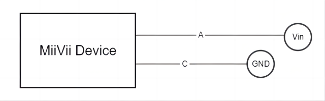
Electrical indicators |
Detailed Parameters |
|---|---|
Vin range |
0~48V |
Logic high-level threshold (output logic 1) |
2.4V≤Vin≤48V |
Logical low level threshold (output logic 0) |
0V≤Vin≤1.2V |
IO rate |
≤100KHz |
Requirements for the peer interface |
The series resistance of the opposite interface to GND is less than 1KΩ |
Usage#
The usage of GPIO is as below
sudo /opt/miivii/features/gpio/bin/miivii_get_di_value <DI number>
#<DI number>: Represents the sequence number of the DI. 0 represents DI0, 1 represents DI1, and so on.
#The command return value is the current level value read from the DI, where 0 represents low level and 1 represents high level.

#Example: Read the input of DI0
#sudo /opt/miivii/features/gpio/bin/miivii_get_di_value 0
Compile sample code
cp -r /opt/miivii/features ~/
cd ~/features/gpio
sudo make;
Troubleshooting of GPIO issues#
Phenomenon: The serial port cannot communicate after the device is powered on. Solution:#
I. Hardware environment inspection operation steps:#
Check the physical interface status:
1) Observe whether there is physical damage such as deformation, breakage, or oxidation on the serial port interface.
2) If damage is found: Contact the device manufacturer’s after-sales service.
Cross-validation test:
Method 1: Connect the serial cable and peripheral device to another normal device and test whether communication is possible:
1) If the other device is normal → The current device has a hardware failure and after-sales service needs to be contacted;
2) If the other device is abnormal → Check whether the cable or peripheral device is damaged.
Method 2 (when there is no other device): Use a test cable to short-circuit two serial ports of the current device (for example, serial port A and serial port B), and test self-transmission and self-reception through a serial port debugging tool:
1) If the transmission and reception are normal → The original peripheral device or cable is faulty;
2) If the transmission and reception fail → The device hardware or system is abnormal.
Short-circuit test:
1) Use a Dupont wire to short-circuit the faulty serial port and other serial ports, and use a serial port debugging tool to verify transmission and reception (Refer to the user manual for the pin definitions of RS232/485/422 and the transmission and reception verification methods).
2) If the two serial ports can communicate normally, it is recommended to check whether there is a fault in the cable and the serial port peripheral device.
3) If the two serial ports cannot communicate normally, execute “Investigation item: Check whether the serial port is correctly configured”.
II. Serial port configuration inspection operation steps:#
1.** **View the current serial port configuration: Enter the command in the terminal (adjust according to the actual serial port node, such as /dev/ttyS0):
# View parameters such as baud rate
stty -F /dev/ttyS0 -a
Key parameters: The baud rate must be exactly the same as that of the peripheral device (such as 115200, 9600, etc.).
2、Fix configuration issues:
If the baud rate is inconsistent: Modify the serial port configuration to match the peripheral device (administrator privileges are required):
# Example: Set the baud rate to 115200
stty -F /dev/ttyS0 115200
If the failure persists even with consistent configurations: Proceed to the system image verification and troubleshooting.
III. Operation steps for system image verification:#
Re - flash the system image: Obtain the latest system image file from the device manufacturer and complete the flashing (backup data before operation).
Verification after flashing: 1) If communication is restored → The original system software environment is abnormal, and you need to check the configuration by yourself. 2) If it is still abnormal → Run the diagnostic script and submit the log:
# RS232串口诊断(示例)
curl -sSL https://support.example.com/diagnose_rs232.sh | sh
# RS485/422串口诊断(示例)
curl -sSL https://support.example.com/diagnose_rs485.sh | sh