BRD601 THOR 40PIN DEBUG Interface#
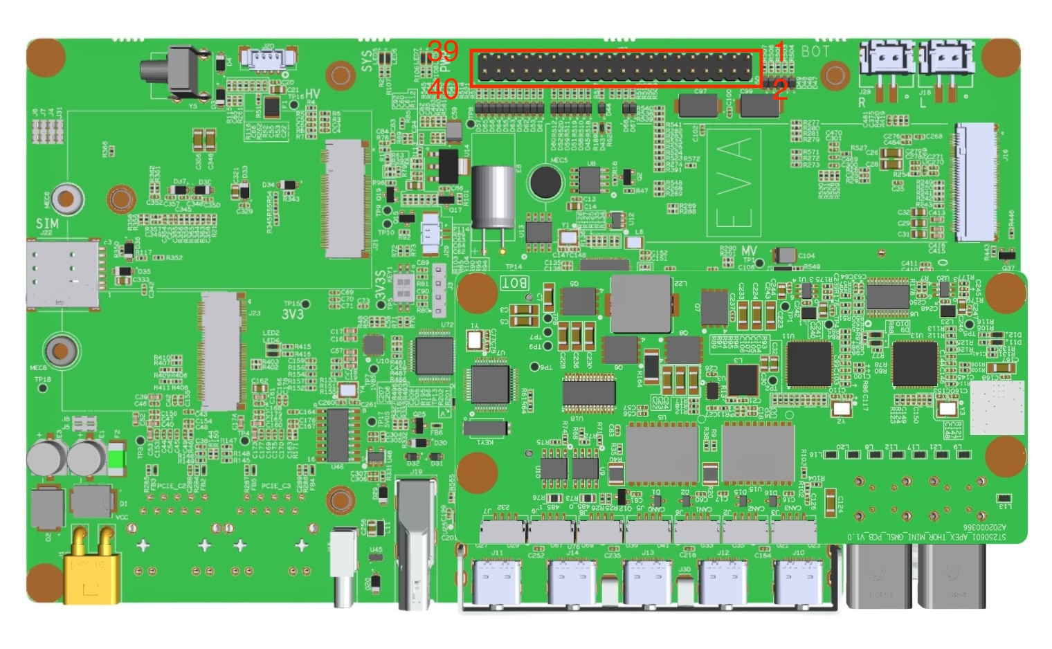
Hardware specifications#
编号 |
功能 |
编号 |
功能 |
|---|---|---|---|
1 |
JTAG_TMS |
2 |
VDD_3V3 |
3 |
JTAG_TDO |
4 |
GND |
5 |
N/A |
6 |
GND |
7 |
JTAG_TDI |
8 |
GND |
9 |
JTAG_TRST_N |
10 |
GND |
11 |
JTAG_TCK |
12 |
GND |
13 |
GND |
14 |
GND |
15 |
NVDEG_SEI |
16 |
NVJTAG_SEI |
17 |
POWER_BTN_CON |
18 |
GND |
19 |
RECOVERY_BTN_CON |
20 |
GND |
21 |
RST_BTN_CON |
22 |
GND |
23 |
SLEEP_BTN_CON(GPIO46) |
24 |
GND |
25 |
SYNC_OUT |
26 |
SPI3_CLK |
27 |
GND |
28 |
SPI3_MISO |
29 |
GND |
30 |
SPI3_MOSI |
31 |
I2C8_CLK |
32 |
SPI3_CS0_N |
33 |
I2C8_DAT |
34 |
SPI3_CS1_N |
35 |
GPIO45/FAN_TACH |
36 |
GPIO36/FAN_PWM |
37 |
GPIO13 |
38 |
GPIO14 |
39 |
GPIO17 |
40 |
GPIO42 |
As shown in the figure, the pin at the top right corner is PIN 1, the pin at the bottom right corner is PIN 2, and so on.
I2C mapping: The device file corresponding to I2C is /dev/i2c-7.
Level standards:
3.3V level signals: JTAG_TMS, VDD_3V3, JTAG_TDO, JTAG_TDI, JTAG_TRST_N, JTAG_TCK, POWER_BTN_CON, RECOVERY_BTN_CON, RST_BTN_CON, SLEEP_BTN_CON (GPIO46), SYNC_OUT.
1.8V level signals: NVDEG_SEI, NVITAG_SEI, SPI3_CLK, SPI3_MISO, SPI3_MOSI, I2C8_CLK, SPI3_CS0_N, I2C8_DAT, SPI3_CS1_N, GPIO45/FAN_TACH, GPIO36/FAN_PWM, GPIO13, GPIO14, GPIO17, GPIO42.
Interface usage#
Function Name |
Usage method |
Function Description |
|---|---|---|
RESET |
Use DuPont wires to short-circuit PIN21 and PIN22 to simulate a button press |
Press the device briefly to restart it |
POWER |
Use a DuPont wire to short-circuit PIN17 and PIN18 to simulate a button press |
In the shutdown state, press the device briefly to start it. |
RECOVERY |
Use a DuPont wire to short-circuit PIN19 and PIN20 to simulate a button press |
Press and hold it before powering on, and keep holding it for more than 3 seconds after powering on to enter the flashing mode. |