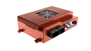
Apex Xavier II+ SYNC IO Usage#
SYNC IN#
Hardware Specification#

SYNC_IO DB9 Port Pin Definition:

Pin |
Signal |
|---|---|
1 |
SYNC_IN_A |
2 |
SYNC_OUT_A |
3 |
NC |
6 |
GND |
7 |
GND |
8 |
GND |
Pin |
Specification |
|---|---|
SYNC_OUT_A |
3.3V |
SYNC_IN_A |
(Logic High 1V-12V, Logic Low 0V-0.8V) |
Method of Application#
The main purpose of SYNC IN is to accept GPS PPS signal input. Cooperate with the GPRMC information received by the serial port to achieve the timing of the system through the external GPS.

Sync in Method#
Sensors with sync-in mode could generate a signal at the beginning of data acquisition. MiiVii device receives this signal and records its rising edge moment. After data acquisition, MiiVii device associates received data with the signal’s rising edge moment as data timestamp. Thus, MiiVii device system obtains data acquisition time.
Figure Sync in Method Schematic (10Hz)

Synchronization Verification:
Print the signal’s timestamp received by SYNC_IN pin. Compare this timestamp with system time of frame received (ros::time::now). If the difference is less than 100 ms, it means sync-in method is functional.
SYNC OUT#
The main purpose of SYNC OUT is to allow the system to trigger external cameras at a fixed frequency.

Hardware Specification#
Refer to the SYNC IN section.
Method of Application#
Sync out Method#
The device can output a 1-30Hz pulse signal with a pulse width of 5ms through the Sync out pin to trigger an external sensor to start sampling. At the same time, the device will record the generation time of the rising edge of the pulse. After the sensor finishes sampling, the device will correlate the recorded time with the data sent back from this sensing as the timestamp of the data. So far, the system has obtained the system time of the sensor sampling and completed the synchronization.
Sync out Method Schematic (25Hz)

At the same time, the device also provides Sync Out synchronization function through the GMSL interface, please refer to the GMSL camera section for details.
Verification method for the synchronization function: Configure the sensor in external trigger synchronization mode and use ROSbag to capture packets to confirm if the sensor trigger frequency matches the frequency set in sync.cfg. If the deviation is less than 1Hz, it indicates that the Sync Out function is effective.
Data transfer time analysis
Test description: Set the frequency of Sync Out signal to 10Hz and measure the time interval (transfer time) from the rising edge of the Sync Out signal sent by the device to the device receiving the video frame.
IO Frame Transfer Timing Diagram.

Test Results of Frame Transfer Time.

The measurement results show that the average frame transfer time is 65.70ms.
