EVO ORIN DO Usage#
Hardware specifications#
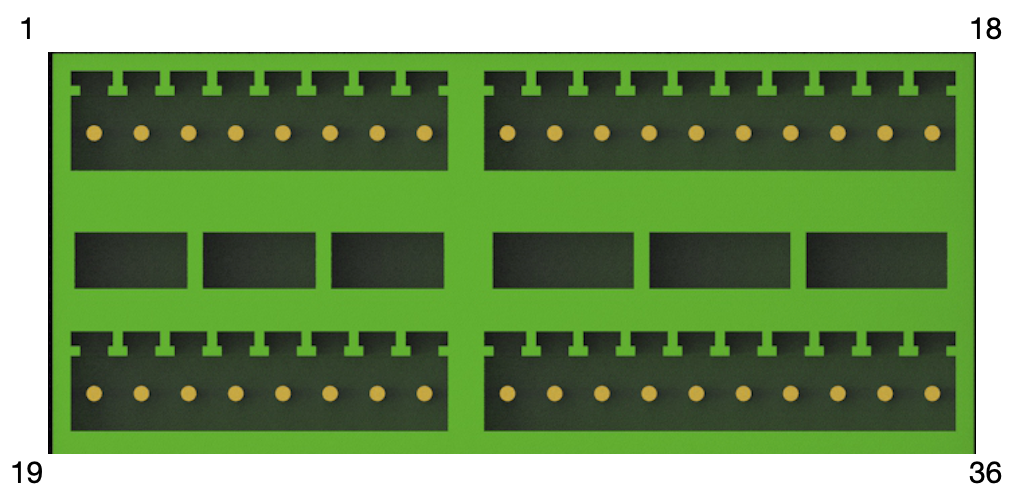
Interface |
Pin Number |
Description |
PIN No. |
Device Node |
|---|---|---|---|---|
DI_1 |
1 |
GPIO IN |
308 |
di1 |
DI_2 |
3 |
GPIO IN |
309 |
di2 |
DI_3 |
5 |
GPIO IN |
310 |
di3 |
DI_4 |
7 |
GPIO IN |
311 |
di4 |
DI_5 |
9 |
GPIO IN |
312 |
di5 |
DI_6 |
11 |
GPIO IN |
313 |
di6 |
DI_7 |
13 |
GPIO IN |
314 |
di7 |
DI_8 |
15 |
GPIO IN |
315 |
di8 |
DO_1 |
19 |
GPIO OUT |
300 |
do1 |
DO_2 |
21 |
GPIO OUT |
301 |
do2 |
DO_3 |
23 |
GPIO OUT |
302 |
do3 |
DO_4 |
25 |
GPIO OUT |
303 |
do4 |
DO_5 |
27 |
GPIO OUT |
304 |
do5 |
DO_6 |
29 |
GPIO OUT |
305 |
do6 |
DO_7 |
31 |
GPIO OUT |
306 |
do7 |
DO_8 |
33 |
GPIO OUT |
307 |
do8 |
GND |
2、4、6、8、10、12、14、16、18、20、22、 24、26、28、30、32、34、36 |
Ground |
||
DC 5V |
17 |
DC 5V OUT |
||
DC 12V |
35 |
DC 12V OUT |
Electrical Characteristics#
Spec |
|
|---|---|
Vout |
0~48V(Support 3.3V,5V,12V,24V,48V),Maximum driving current 20mA |
Description |
Conditions of application |
|
|---|---|---|
Vref |
User external power supply |
3.3V~48V |
R |
User external pull-up resistor |
R>Vref/0.02 (0,02 is the maximum value of DO chip drive current) R(The resistor package tolerates power)>Idrv²*R(Idrv = Vref/R) |
Vout |
When the output logic is high,Vout = Vref When the output logic is low,Vout = 0 |
Vout is used for IO ports of external devices The external power supply is forbidden to connect directly to the Vout, otherwise it causes the Vout port to start passive protection, resulting in abnormal IO signal. |
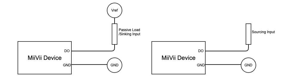
Description |
|
|---|---|
Vref |
Voltage to be supplied externally at the user side. |
Passive Load |
E.g. LED, Relay, Solenoid Valve. |
Active Sourcing Input |
Active Sourcing Input, DI of PLC, e.g. |
Target pull-up voltage(V) |
3.3V |
5V |
12V |
15V |
24V |
36V |
48V |
|---|---|---|---|---|---|---|---|
Pull-up resistors(Ω) |
500Ω |
1kΩ |
2kΩ |
3kΩ |
5kΩ |
10kΩ |
10kΩ |
Software Usage#
System version below 5.x.x-x.x.x#
The example of using the GPIO interface is as follows.
# Use root
sudo su -

# Set output to high
echo 1 > /sys/class/gpio/<device node>/value
# Example: echo 1 > /sys/class/gpio/gpio339/value

# Set output to low
echo 0 > /sys/class/gpio/<device node>/value
# Example: echo 0 > /sys/class/gpio/gpio339/value
System version above 6.x.x-x.x.x#
The usage of GPIO is as below
sudo /opt/miivii/features/gpio/bin/miivii_set_do_level <DO number> <level: 0/1> <duration(seconds) of level>
#<DO number>: Represents the sequence number of the DO. 0 represents DO1, 1 represents DO1, and so on.
#<level: 0/1>: Represents the level to be set. 0 represents low level, and 1 represents high level.
#<duration(seconds) of level>: The duration of the level in seconds. During this period, the DO level will be in the state specified by <level: 0/1>. After the level duration is exceeded, the DO returns to its previous state.

#Please note that starting from Linux kernel version 4.8, the GPIO SYSFS interface is marked as deprecated and is no longer supported in Jetpack 6.0 and later versions. It is recommended to use libgpiod for GPIO operations. Therefore, setting the level without specifying a duration is not supported.
#Example: Set DO0 to high level with a duration of 20 seconds.
#sudo /opt/miivii/features/gpio/bin/miivii_set_do_level 0 1 20
Compile sample code
cp -r /opt/miivii/features ~/
cd ~/features/gpio
sudo make;