Notice
Please read manual carefully before install, operate, or transport MiiVii device.
Ensure that the correct power range is being used before powering the device.
Avoid hot plugging.
To properly turn off the power, please shut down the Ubuntu system first, and then cut off the power. Due to the particularity of the Ubuntu system, on the Nvidia developer kit, if the power is turned off when the startup is not completed, there will be a 0.03% probability of abnormality, which will cause the device to fail to start. Due to the use of the Ubuntu system, the same problem also exists on the Miivii device.
Do not use cables or connectors other than described in this manual.
Do not use MiiVii device near strong magnetic fields.
Backup your data before transportation or MiiVii device is idle.
Recommend to transport MiiVii device in its original packaging.
Service and support
Technical support
If you encounter problems or you think your product is defective, please email: helpdesk@miivii.com , we will help you solve the problem. You can also visit the MiiVii Technology Forum http://forum.miivii.com , search our knowledge base for solutions to common problems.
Warranty
Warranty period: the warranty period of MiiVii equipment is one year from the date of purchase. Warranty regulations: during the warranty period, if there is any non-human damage to the product, MiiVii will provide free warranty. Please contact helpdesk@miivii.com Get warranty assistance.
Product list
EVO Xavier II×1
ACDC power adatper×1
Power cable x 1
Screws
Fixed plate x 2
DIO extension x 2
Warranty card×1
QC PASS×1
Table of contents
About EVO Xavier II
MIIVII EVO Xavier II is an embedded edge AI platform designed for industrial application.It Supports NVIDIA® Jetson AGX Xavier, featuring over 30TOPs in INT8 for real-time inference.High efficiency of active and passive heat dissipation design, can work stably in harsh industrial environment,The fastening embedded design provides high vibration resistance。 The EVO Xavier II provides a rich I/O interface that can meet the access requirements of a variety of dedicated sensors, while providing efficient sensor clock synchronization,A variety of internal expansion interfaces to provide more wireless communication and storage expansion solutions.

Front view | Side view |
|---|---|
|
|
| Top view | rear view |
|
|

Specifications
Processor
Specification | |
|---|---|
Processor | NVIDIA Jetson AGX Xavier |
| AI Performance | Up to 32T OPS |
| CPU | 8-core ARM v8.2 64-bit CPU |
| GPU | 512-core Volta GPU |
| Memory | 32GB 256-Bit LPDDR41 |
| DL Accelerator | 2×NV DLA Engines |
| Storage | 32GB eMMC 5.1 |
| Video Encode | 4x 4Kp60 4x 4Kp60 |
| Video Decode | 2x 8Kp30 4x 4Kp60 |
I/O
| Interface | Quantity | Note | |
| Function KEY | Power Button | 1 | |
| Recovery Button | 1 | ||
| Network/Camera | Ethernet | 5×Gigabit Port | Optional: 4×PoE+ ,IEEE 802.3 af PoE 15.4W(max) |
| Video output | HDMI | 1×HDMI 2.0 TYPE A | 5V 1A |
| USB | USB | 4×USB 3.0 TYPE A 1×USB 2.0 TYPE C | USB 5V, 1A USB 2.0 Flashing Port |
| I/O | UART | 3xRS232 2xRS485 1xDebug | DB9 Terminal RS232_sync FOR GPS Time Synchronize |
| SYNC I/O | 1×PPS_IN 1×PPS_OUT 2×SYNC_OUT | 1 x pps in with TTL,UART with RS232 1 x pps out with TTL,UART with RS232 2 x Sync out with TTL | |
| CAN | 2 | Two CAN in One DB9 Terminal With CAN chip, terminal resistor 120Ω | |
| GPIO | 8xIsolated DI Output Voltage 1x DC5V、1xDC12V(Input Voltage Need 14-48V) | DI 5-48V DC | |
User Expansion | TF Socket | 1xTF Slot | MicroSD card supported |
| M.2 | 1×M.2 M Key 1×M.2 B Key | M.2 M Key 2280 SIZE NVME SSD M.2 B Key For 5G | |
| Mini PCle | 2 | For WIFI or 4G expansion | |
| Nano SIM Socket | 4 | For Nano SIM Card |
Power Supply
Power Supply | Spec |
|---|---|
| Input Type | DC |
| Input Voltage | Wide input 12-48V 24-48V for PoE(Optional) |
| Typical consumption | 50W |
Mechanical
Mechanical | Spec |
|---|---|
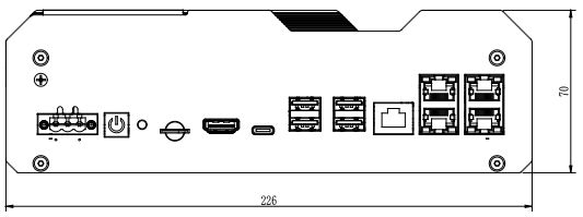
| Dimensions (W×H×D) | 226mm×70mm×144.5mm (I/O ports and mounting holes excluded) |
| Weight | 2.3Kg |
Environmental
Environmental | Spec |
|---|---|
| Operating Temperature | -20℃-60℃ |
| Storage Temperature | -25℃-80℃ |
| Storage Humidity | 10%-90% non-condensing |
| Vibration | 3 Grms,10Hz~500Hz,1h/axis |
| Protection | IP5X |
| ESD | Touch 6KV, Air 8KV |
Certification
Certification | Status |
|---|---|
| CCC, CE, FCC, RoHS | Processing |
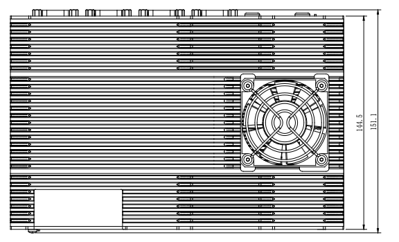
Install Dimension
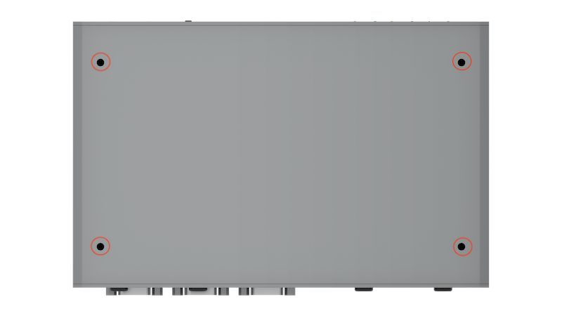
Dimensions and mounting hole position as below:
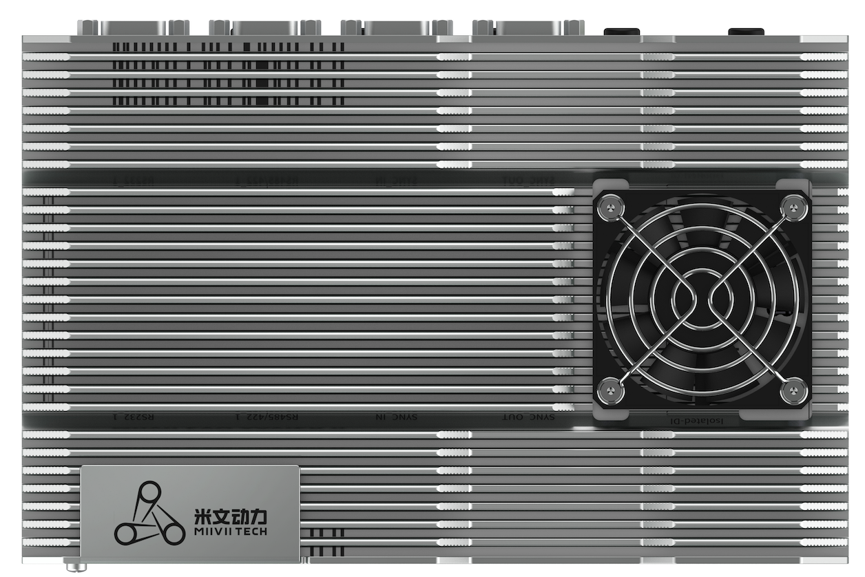
Up view(Unit:mm) |
|---|
|
| Front view(Unit:mm) |
|
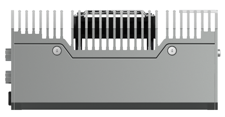
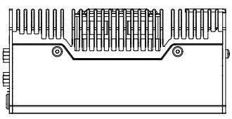
| Left view(Unit:mm) |
|
| 1 Mounting Hole(Unit:mm) |
|
| 2 Mounting Hole(Unit:mm) |
|

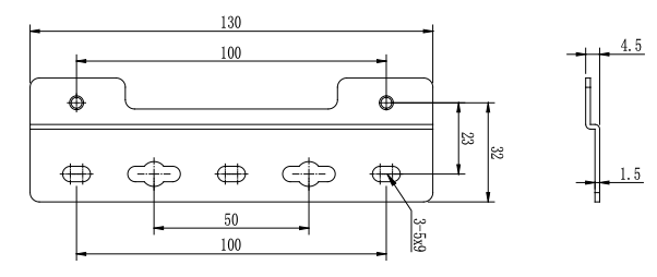
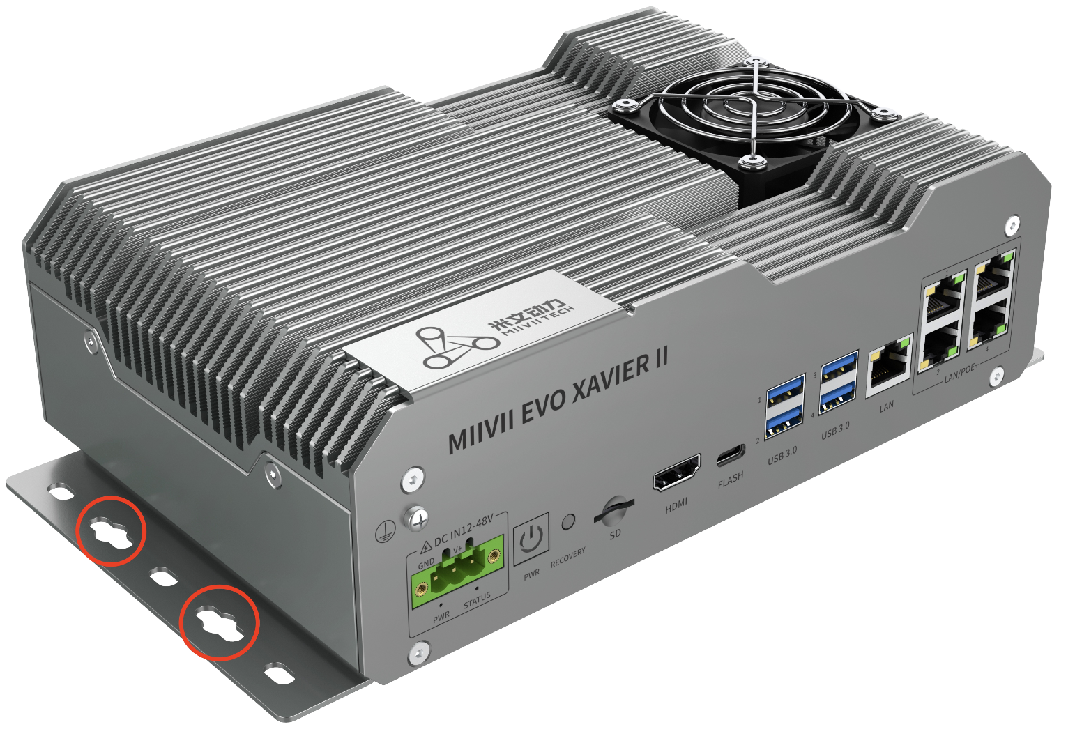
Fixed Plate installation
Please install fixed plate first if you need to securing EVO Xavier II on another system.
|
|---|
Figure Fixed Plate1 |
|
|---|
| Figure Fixed Plate2 |
Chapter 一:Device Interface Description
Interface description
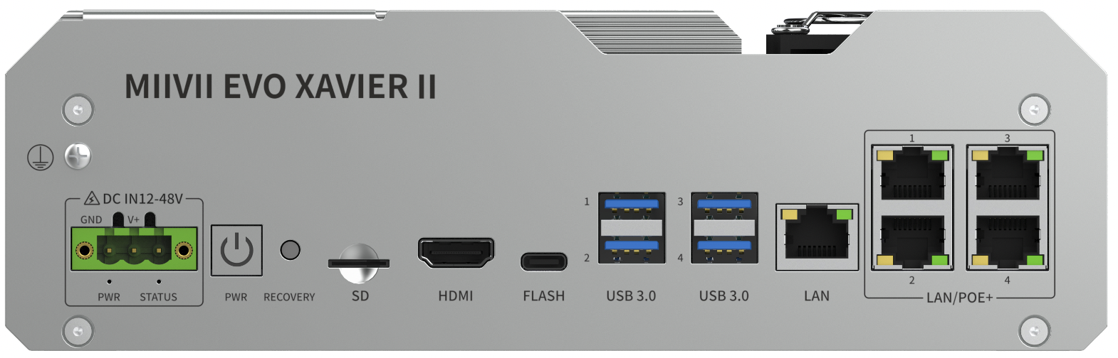
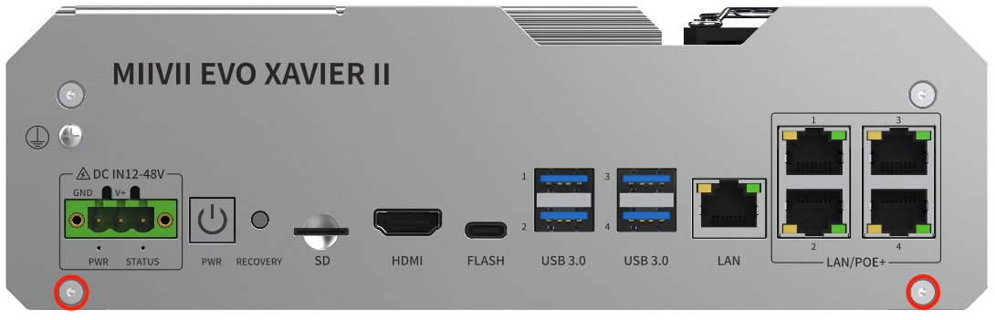
Front Panel
|
|---|
Figure EVO Xavier II Front Panel |

Interface | Interface Name | Description |
|---|---|---|
| DC IN | Power Interface | Power input voltage12V~48V |
| PWR_LED | Carrier board status indicator | Carrier board power on: solid yellow Carrier board system on: solid white Carrier board system error: solid red |
| STATUS | System status indicator | System on: solid blue System off: solid red |
| PWR_Button | Power Button | |
| RECOVERY | Recovery Button | Inter Recovery mode while pressing |
| SD | TF socket | For TF card 3.3V 1A |
| HDMI | HDMI | HDMI 2.0 TYPE A 5V 1A |
| USB 3.0×4 | USB 3.0 port | 4 x USB3.0 5V 1A |
| LAN×5 | Ethernet | Independent gigabit network port, compatible with 100Mbps network port Optional IEEE 802.3af POE 15.4w |
| FLASH | USB 2.0 TypeC port | Indenpendent USB 2.0 flashing port 5V 1A |
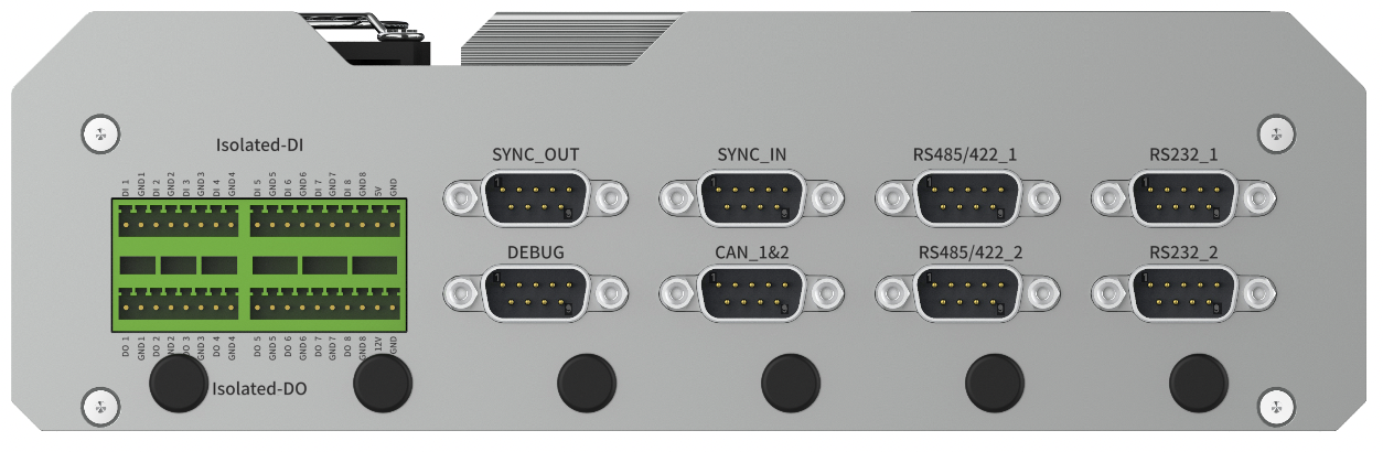
Back Panel
|
|---|
Figure EVO Xavier II Back Panel |
Interface | Interface Name | Description |
|---|---|---|
| DI | DI port | DI 5V~48V DC |
| DO | DO port | DO 3.3V~48V DC |
| SYNC_OUT | Sync out port | 2 x Sync out with TTL 1 x pps out with TTL,UART with RS232 |
| SYNC_IN | Sync in port | 1 x pps in with TTL,UART with RS232 |
| DEBUG | 调试接口 | RS232 |
| CAN_1&2 | CAN接口1号及2号 | CAN FD,Two CAN in One DB9 Terminal terminal resistor 120Ω |
| RS485/422_1 | RS485/422串口1号 | RS422 and RS485 compatible in One DB9 Terminal |
| RS485/422_2 | RS485/422串口2号 | RS422 and RS485 compatible in One DB9 Terminal |
| RS232_1 | RS232串口1号 | RS232 |
| RS232_2 | RS232串口2号 | RS232 |
Chapter 二:GPIO port and function introduction
GPIO Port pin Assignment
|
|---|
Figure DI/DO Pin Assignment |
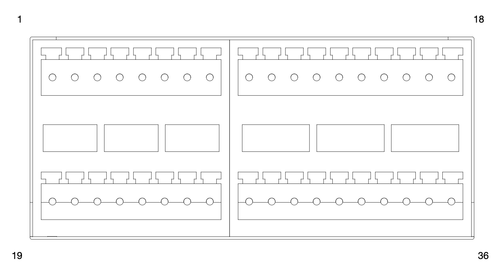
Interface | Pin | Signal | Description | GPIO Chip |
| DI | 1 | DI_1 | DI_1 input 0:0V~3V 1:5V~48V | 240 |
| 2 | GND_1 | GND_1 | ||
| 3 | DI_2 | DI_2 input 0:0V~3V 1:5V~48V | 241 | |
| 4 | GND_2 | GND_2 | ||
| 5 | DI_3 | DI_3 input 0:0V~3V 1:5V~48V | 242 | |
| 6 | GND_3 | GND_3 | ||
| 7 | DI_4 | DI_4 input 0:0V~3V 1:5V~48V | 243 | |
| 8 | GND_4 | GND_4 | ||
| 9 | DI_5 | DI_5 input 0:0V~3V 1:5V~48V | 244 | |
| 10 | GND_5 | GND_5 | ||
| 11 | DI_6 | DI_6 input 0:0V~3V 1:5V~48V | 245 | |
| 12 | GND_6 | GND_6 | ||
| 13 | DI_7 | DI_7 input 0:0V~3V 1:5V~48V | 246 | |
| 14 | GND_7 | GND_7 | ||
| 15 | DI_8 | DI_8 input 0:0V~3V 1:5V~48V | 247 | |
| 16 | GND_8 | GND_8 | ||
| DC5V | 17 | DC 5V | DC 5V 1A out put | |
| 18 | GND | DC 5V GND | ||
| DO | 19 | DO_1 | DO_1 output 3.3~48V , 20mA max | 232 |
| 20 | GND_1 | GND_1 | ||
| 21 | DO_2 | DO_2 output 3.3~48V,20mA max | 233 | |
| 22 | GND_2 | GND_2 | ||
| 23 | DO_3 | DO_3 output 3.3~48V,20mA max | 234 | |
| 24 | GND_3 | GND_3 | ||
| 25 | DO_4 | DO_4 output 3.3~48V,20mA max | 235 | |
| 26 | GND_4 | GND_4 | ||
| 27 | DO_5 | DO_5 output 3.3~48V,20mA max | 236 | |
| 28 | GND_5 | GND_5 | ||
| 29 | DO_6 | DO_6 output 3.3~48V,20mA max | 237 | |
| 30 | GND_6 | GND_6 | ||
| 31 | DO_7 | DO_7 output 3.3~48V,20mA max | 238 | |
| 32 | GND_7 | GND_7 | ||
| 33 | DO_8 | DO_8 output 3.3~48V,20mA max | 239 | |
| 34 | GND_8 | GND_8 | ||
| DC12V | 35 | DC12V | DC12V 1A output (Input Voltage Need 14-48V) | |
| 36 | GND | DC12V GND |
GPIO interface configuration method
The example of GPIO interface is as follows. Please modify the < > information to the GPIO node number to be adjusted. For the specific correspondence, please refer to the [pin number] section
# 切换到root用户
sudo su -
# 设置为高电平(DO)
echo 1 > /sys/class/gpio/<gpio339>/value
# 设置为低电平(DO)
echo 0 > /sys/class/gpio/<gpio339>/value
# 读取数据(DI)
cat /sys/class/gpio/<gpio339>/value
If you need to preserve the configuration after shutdown, you can write the above command to / etc / RC Local file
Description of GPIO output mode of MIIVII device
Target pull-up voltage(V) | 3.3V | 5V | 12V | 15V | 24V | 36V | 48V |
|---|---|---|---|---|---|---|---|
Pull-up resistors(Ω) | 500Ω | 1kΩ | 2kΩ | 3kΩ | 5kΩ | 10kΩ | 10kΩ |
Chapter 三:Introduction to synchronization interface and related functions
SYNC_IN Pin Assignment
|
|---|
Figure SYNC_IN Pin Assignment |

| Interface | Pin | Signal | Description | Device Node |
| SYNC_IN | 1 | PPS_GND | PPS GND is exclusive used for Sync function, isolated from GND | ttyUART_232_sync |
| 2 | RS232_RX | RS232 recieve | ||
| 3 | RS232_TX | RS232 transmit | ||
| 4 | NC | NC | ||
| 5 | GND | GND for RS232 | ||
| 6 | PPS_IN | PPS IN with TTL | ||
| 7 | NC | NC | ||
| 8 | NC | NC | ||
| 9 | NC | NC |
External GPS sync
The NMEA output serial port of GPS connects with UART SYNC_IN hardware serial port of EVO Xavier II(the baud rate of serial port is 9600), and the mapping to Linux system is / dev / ttyuart_ 232_ sync equipment node.
The PPS second pulse output signal line of GPS is connected to the sync of EVO Xavier II_ Pin6 pin of IO line is mapped to Linux system as / dev / miivii-sync-in-a device node.
In GPS timing mode, the above two nodes will be occupied by the background GPS timing processing program. Do not perform other operations on these two nodes, otherwise the GPS timing function will be interrupted.
Baud rate adjustment of GPS timing serial port
The baud rate of GPS timing serial port node is adjustable:
In / etc / SYSTEMd / sync_ auto. SH script, as follows:
For example: change to 115200
/usr/local/bin/sync_ auto 115200 > /var/log/miivii_ sync. log &
If the baud rate parameter is not filled in, it defaults to 9600
The baud rate parameters supported are as follows:
2400 4800 9600 57600 115200 460800
Use GPS To Give Time To The Device
Advantages of GPS timing function: The device obtains local standard time signal from GPS satellite through GPS device, so as to accurately locate the device time
GPS Support Model
The serial port supports modifying baud rate. The default baud rate is 9600 GPS brand supported: all GPS devices that conform to GPRMC data standard format output and must have PPS second pulse output
Connection Mode
Refer to the "Interface Description" in the manual.
Timing Function Configuration
When the GPS is connected for the first time, the system configuration should be conducted in MiiVii Setting configuration software. Configure the Sync Mode option to GPS Mode and restart the system.Please refer to the section of "MiiVii Setting" for specific methods.
Check Whether The Timing Was Successful
Modify the system time, enter the command
sudo date -s "2018-10-1"
Wait for 2~3s, check the current time, and enter the command
data
If the display time is: "2018-10-1", it means the timing failed If the display time is: "current time", the timing is successful
Troubleshooting
If the timing fails, fault troubleshooting shall be carried out
1. Check If The GPS Has Output
Type the command
cat /dev/ttyTHS1
The terminal receives output with a GPRMC field, such as: GPRMC,014600.00,A,2237.496474,N,11356.089515,E,0.0,225.5,310518,2.3,W,A*23
2. Check The OUTPUT of THE GPS PPS Signal
Type the command
hexdump /dev/miivii-sync-in-a
The terminal has hexadecimal data output, such as: 0000400 02fe 9f40 490e 562d 1647 004e 0000 0000
3. Identify Methods
If the above "1"&"2" has no output, indicating that the GPS is not working properly, you can put the GPS out of the window or go outside for testing, or change the GPS for testing
If the output of "1"&"2" is normal, check whether the MiiVii Setting configuration is in GPS mode. If not, change the mode and restart it
After the above operation, GPS timing is still unsuccessful, enter the command
hexdump /dev/miivii-sync-out
The terminal has hexadecimal data output, such as: 0000400 02fe 9f40 490e 562d 1647 004e 0000 0000
If there is no data output, it may be that there is no matching brush tool and mirror brush. It is recommended to check the mirror and the brush tool to re-brush
If there is data output, it may be a hardware problem,it is recommended to contact after-sales maintenance treatment
SYNC_OUT Pin Assignment
|
|---|
Figure SYNC_OUT Pin Assignment |
Interface | Pin | Signal | Description |
| SYNC_OUT | 1 | PPS_GND | GND for PPS_OUT |
| 2 | RS232_RX | RS232 recieve | |
| 3 | RS232_TX | RS232 transmit | |
| 4 | SYNC_OUT1 | SYNC_OUT1 with TTL | |
| 5 | GND | GND for RS232 | |
| 6 | PPS_OUT | PPS OUT with TTL | |
| 7 | SYNC_OUT1_GND | GND for SYNC_OUT1 | |
| 8 | SYNC_OUT2_GND | GND for SYNC_OUT2 | |
| 9 | SYNC_OUT2 | SYNC_OUT2 with TTL |
Synchronization function instructions
The device supports two synchronization methods, namely: PPS and Sync out synchronization. The synchronization error is 0.1-1 μs.
|
|---|
Figure, Schematic diagram of equipment synchronization wiring |

How to use the sync function
PPS sync mode
The device outputs PPS signal7 (one pulse is generated per second with a pulse width of 50ms), and sends NMEA GPRMC message of the generation time of the rising edge of the pulse through TX pin of serial port (UART / RS232). Message example:
$GPRMC,060249.000,A,3949.63046,N,11616.48565,E,0.296,,291118,,,A*4d
7 for the hardware connection mode of PPS signal, see "PPS connection line and pin definition" in "Introduction to synchronous interface and related functions"
Where "060249.000" is the time stamp (UTC time) when the pulse is generated per second. The format is "hour minute second. 000", and the normal time is in the whole second format. Sensors supporting PPS synchronization mode will calibrate their own clock system through the received PPS and GPRMC messages to keep it consistent with the system clock of the equipment. The sampling time of the sensor will be sent to the device together with the data as a timestamp. So far, the system obtains the system time of sensor sampling and completes the synchronization.
|
|---|
Figure PPS synchronization schematic diagram |

Synchronization verification (RS-LiDar-16 sensor):
When the sensor connects with EVO Xavier II using only data wire, device ROS Node sends hardware timestamp to the system, which is determined by sensor’s internal clock. As shown below, there is a big difference between hardware timestamp and system time.
|
|---|
| Figure RS-LiDAR-16 comparison of the timestamps between the hardware and system(before synchronization) |

Sync out
The device supports sync out synchronization signal8
8For the hardware connection mode of sync out signal, see "sync connection line and pin definition" in "Introduction to synchronization interface and related functions"
The device can output a 1-30Hz pulse signal with a pulse width of 5ms through the sync out pin to trigger the external sensor to start sampling. At the same time, the equipment will record the generation time of the rising edge of the pulse. After the sensor completes sampling, the equipment will associate the recorded time with the data returned by the sensor as the time stamp of the data. So far, the system obtains the system time of sensor sampling and completes synchronization.
|
|---|
Figure sync out synchronization schematic diagram (25Hz) |

Chapter 四:CAN port and function introduction
CAN Pin Assignment
|
|---|
Figure CAN Pin Assignment |
Interface | Pin | Signal | Description | Device Node |
| CAN_1&2 | 1 | CAN1_L | CAN_1 Low | CAN_0 & CAN_1 |
| 2 | CAN0_L | CAN_0 Low | ||
| 3 | GND | GND | ||
| 4 | GND | GND | ||
| 5 | NC | NC | ||
| 6 | GND | GND | ||
| 7 | CAN0_H | CAN_0 High | ||
| 8 | CAN1_H | CAN_1 High | ||
| 9 | NC | NC |
Can port configuration method
For the specific use method of can equipment, refer to https://github.com/linux-can/can-utils include cansend.C and candump.c
Test command:
sudo modprobe can

sudo modprobe can_raw

sudo modprobe mttcan

sudo ip link set can0 type can bitrate 500000 sjw 4 berr-reporting on loopback off

sudo ip link set up can0

sudo cansend can0 123#abcdabcd

sudo candump can0

sudo ip -details -statistics link show can0

sudo ifconfig can0 down
Can FD configuration usage method10:
sudo modprobe can

sudo modprobe can_raw

sudo modprobe mttcan

sudo ip link set can0 type can bitrate 500000 sjw 4 dbitrate 2000000 dsjw 4 berr-reporting on fd on

sudo ip link set up can0

sudo cansend can0 213##011
[10] CAN FD和CAN 2.0的区别:
10 difference between can FD and can 2.0:
1)
sudo ip link set can0 type can bitrate 500000 dbitrate 2000000 berr-reporting on fd on
Where bitrate is can2 Baud rate in 0 mode; dbitrate is the baud rate in can FD mode. According to the official document, the maximum value can be configured as 5m. 2m is best for general applications;
2)
sudo cansend can0 213##011
In the send command, there is an # between the ID and the data, and the first byte (0) after the ## is canfd_ frame. The value of flags, ranging from 0 to f; canfd_ frame. The byte (11) after flags is the first data, and a maximum of 64 bytes can be transmitted at a time.
Chapter五:UART port and function introduction
RS485/422 Pin Assignment
|
|---|
Figure RS485/422 Pin Assignment |
| Interface | Pin | Signal | Description | Device Node |
| RS485/422_1 | 1 | TXD+/Data+ | UART(422_1_T+/485_1_A) | ttyUART_485_422_1 |
| 2 | TXD-/Data- | UART(422_1_T-/485_1_B) | ||
| 3 | RXD+ | UART 422_1_R+ | ||
| 4 | RXD- | UART 422_1_R- | ||
| 5 | GND | GND | ||
| 6-9 | NC | NC | ||
| RS485/422_2 | 1 | TXD+/Data+ | UART(422_2_T+/485_2_A) | ttyUART_485_422_2 |
| 2 | TXD-/Data- | UART(422_2_T-/485_2_B) | ||
| 3 | RXD+ | UART 422_2_R+ | ||
| 4 | RXD- | UART 422_2_R- | ||
| 5 | GND | GND | ||
| 6-9 | NC | NC |
RS232 Pin Assignment
|
|---|
Figure RS232 Pin Assignment |
| Interface | Pin | Signal | Description | Device Node |
| RS232_1 | 1 | NC | NC | ttyUART_232_1 |
| 2 | UART1_RX_232 | RS232_1 receive | ||
| 3 | UART1_TX_232 | RS232_1 transmit | ||
| 4 | NC | NC | ||
| 5 | GND | GND | ||
| 6-9 | NC | NC | ||
| RS232_2 | 1 | NC | NC | ttyUART_232_2 |
| 2 | UART2_RX_232 | RS232_2 receive | ||
| 3 | UART2_TX_232 | RS232_2 transmit | ||
| 4 | NC | NC | ||
| 5 | GND | GND | ||
| 6-9 | NC | NC |
UART interface configuration method
Open the corresponding device node under / dev / < device node number >, and set baud rate, stop bit, parity bit, data bit, etc. You can use the stty command to configure the baud rate, stop bit, parity bit, data bit, etc. of the serial port. See the description of the stty command for details.
For the command example, please modify the < > information to the serial port node number to be adjusted. For the specific correspondence, please refer to the [equipment node number] section
sudo stty -F /dev/<UART_XXX> speed 115200 cs8 -parenb -cstopb -echo
Output data test
sudo echo “miivii tty debug” > /dev/<UART_XXX>
Use the following command to receive input data
sudo cat /dev/<UART_XXX>
Chapter六:Debug Interface Description
Debug Pin Assignment
|
|---|
Figure Debug Pin Assignment |
| Interface | Pin | Signal | Description |
| Debug | 1 | NC | NC |
| 2 | UART1_RX_232 | RS232 receive | |
| 3 | UART1_TX_232 | RS232 transmit | |
| 4 | NC | NC | |
| 5 | GND | GND | |
| 6-9 | NC | NC |
Chapter七:Expansion device installation and instructions
Expansion device installation
EVO Xavier II provides M.2 M Key、M.2B Key and mini PCIe port for storage and communication expansion
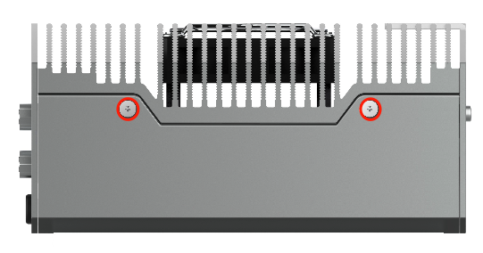
Unscrew 8 screws and take off bottom cover of EVO Xavier while installation expansion device:
|
|---|
Figure EVO Xavier II Screw Position1 |
|
|---|
Figure EVO Xavier II Screw Position2 |

|
|---|
Figure EVO Xavier II Screw Position3 |
|
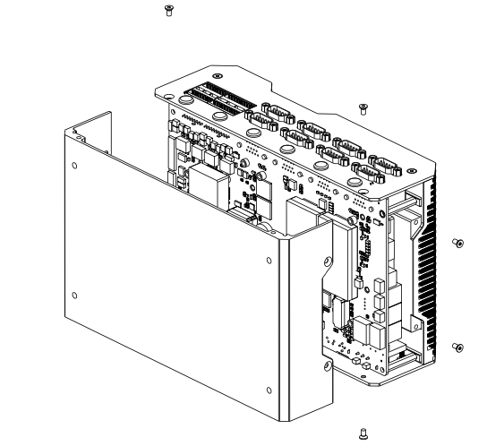
|---|
Figure Remove Bottom Cover |
Expansion port position as follow:
|
|---|
Figure Expansion Port Position |
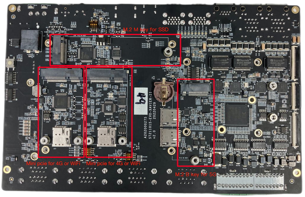
Install expansion device based on demand. Please note that if you need 4G module, insert nano SIM card into nano SIM socket before install 4G module.
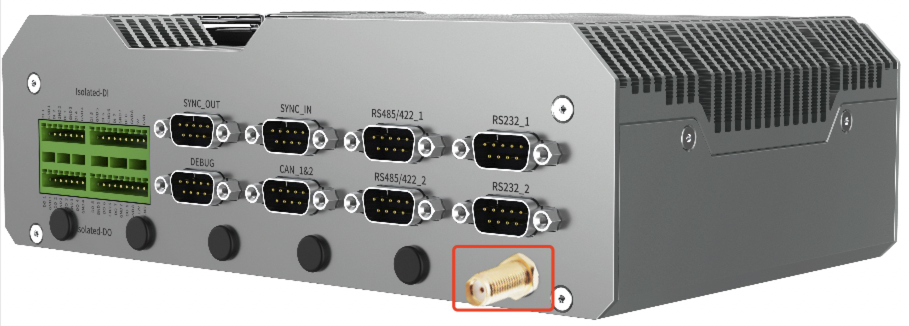
Please install WiFi/4G/5G antenna to ensure signal stability.
|
|---|
| Figure Antenna Installation1 |
|
| Antenna Installation2 |

Please refer to the first step, and restore EVO Xavier II after install expansion device.
Mini PCIe 4G Support List
NO. | Brand | Product NO. | Interface | Function | Working temperature | Specifications | Note |
|---|---|---|---|---|---|---|---|
| 1 | QUECTEL | EC20-CEHCLG-MINIPCIE-CB | Mini PCIe | 4G | -40ºC - 80ºC | All netcom DL:130Mbps Max UL:30Mbps Max |
M.2 B Key 5G Support List
NO. | Brand | Product NO. | Interface | Function | Working temperature | Specifications | Note |
|---|---|---|---|---|---|---|---|
| 1 | QUECTEL | RM500Q-CN | M.2 B Ke | 5G | -20ºC - 60ºC | All netcom SA : DL: 2.1Gbps ; UL:900Mbps NSA : DL: 2.5Gbps ; UL:650Mbps |
4G/5G Setting
4G/5G module is not included in MiiVii device package. Please refer to the information in [Expansion] to install 4G/5G module. Instructions for 4G/5G module configuration are shown as below, using QUECTEL EM05 as an example. EM05 4G driver is included in MiiVii system. This SIM card could be detected automatically. There should be 4 devices under /dev/ttyUSB0~/dev/ttyUSB3 for 4G and 1 devices under /dev/tty UART_AT for 5G.
Users need to choose their own 4G/5G LTE SIM card(note that mobile phone sim card and IOT sim card is supported, but IOT sim card is hardware-binding, please consult your carrier for more information ). Before getting started, please insert SIM card into sim socket.
Mini PCIe WIFI Support List
NO. | Brand | Product NO. | Support | Interface | Function | Working temperature | Standard | Spec | Note |
|---|---|---|---|---|---|---|---|---|---|
| 1 | Azurewave | AW-CB161H | Formal | Mini PCIe | WIFI+BT | 0ºC - 70ºC | Wifi 802.11a/b/g/n/ac BT:4.0 | WIFI rate ≤433.3Mbps |
WiFi Setting
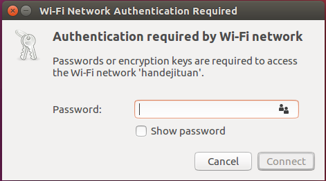
MIIVII EVO XAVIER II provides WiFi function via a expansion module. Please refer to the information in [Expansion] to intall WiFi module. Click the network icon in upper-right corner of the desktop. Find the name of your WiFi network and click on it. Enter your password and click ‘Connect’.
|
|---|
| Figure WiFi Connection |
M. 2 SSD hard disk
Check ssd information:
sudo fdisk -lu
|
|---|
Figure screenshot of viewing hard disk information page |

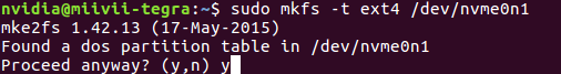
Format hard disk:
sudo mkfs -t ext4 /dev/nvme0n1
|
|---|
Figure screenshot of formatted hard disk |
View hard disk UUID:
sudo blkid /dev/nvme0n1
|
|---|
Figure screenshot of hard disk UUID |

Setting method of automatic mounting SSD: Create a systemd service in the /etc/systemd/system path to automatically mount the SSD when booting, such as: miivii_mount_ssd.service
#创建服务miivii_mount_ssd.service
vim miivii_mount_ssd.service
[Unit]
Description=MIIVII specific script
After=udev.service

[Service]
ExecStart=/etc/systemd/miivii_mount_ssd.sh

[Install]
WantedBy=multi-user.target
Create a script under the path of / etc / SYSTEMd / to mount the hard disk, such as miivii_ mount_ ssd. sh
#创建服务脚本miivii_mount_ssd.sh
vim miivii_mount_ssd.sh
#!/bin/bash
mount -o rw /dev/nvme0n1 /home/nvidia/workspace
change mode for this script
sudo chmod +x miivii_mount_ssd.sh
Set the mounted SSD service to start at boot
sudo systemctl enable miivii_mount_ssd.service
Appendix 1 EVO XAVIER II General usage
system introduction
Miwen devices use Ubuntu 1804 system. Default username: nvidia; password: nvidia
Turn On/Off machine
Boot: The default boot mode of Miivii device is power-on auto-start. Plug in the power supply, and connect the monitor to the Miivii device through the HDMI interface. The startup screen is as shown in the figure:
|
|---|
Figure Desktop Screen |

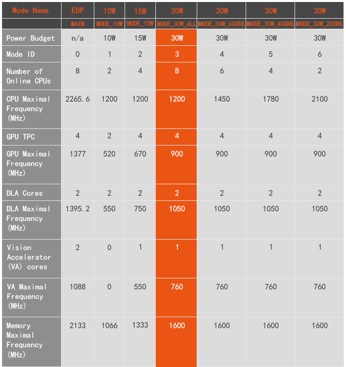
Power Mode Settings
Miivii devices equipped with Jetson AGX Xavier have multiple working modes. This can be adjusted via the NVIDIA green logo setting in the upper right corner. The default mode for Miivii devices is 3: MODE_30W_ALL
|
|---|
Figure Settings Icon |

Click the drop-down menu to modify the working mode of the Miivii device. The details of the working mode are shown in the following table:
You can also use command line adjustments:
#查看设备现在的模式
sudo nvpmodel -q verbose
# 设定为某一模式
sudo nvpmodel -m <MODE ID>
#获取在当前模式下的最佳表现
sudo jetson_clocks
#查看详细信息
sudo jetson_clocks --show
Exception handling
If there is an abnormal situation during the development process, you can first print the log through the DEBUG serial port to judge the problem by yourself. The specific operations are as follows:
Step 1: Find the specific location of the DEBUG interface according to the information in the [Interface Description] section
Step 2: Use an RS232-USB adapter cable to connect the DEBUG interface to the upper computer PC
Step 3: On the PC side of the host computer, download the serial debugging tool and adjust the baud rate to 115200 Baud
Step 4: Grab the serial port log in the serial port debugging tool to analyze abnormal problems
Appendix 2: Image Burning And OTA
Jetpack 4.5 and Above Image Burning
1.Function Introduction
Miivii flash tool, suitable for Miivii series products.
Miivii flash tool is a tool software provided for the convenience of burning, writing, cloning and small batch production of Miivii equipment.
You can burn the Miivii official image to Miivii equipment by using X86 architecture PC as the burning host. After a period of development of Miivii equipment, the existing equipment can be mirrored and cloned to save the development progress, and burned to other Miivii equipment in a single or small batch of products.
Core Function
- Automatic detection of useing environment
- Automatically detect the latest mirror
- Build-in image downloader, no need to download images manually.
- Support batch burning
- Support mirror cloning(It should be noted that you need to use the same Jetpack version before burning after Clone.)
2.Prepare Software and Hardware
2.1. Burning Host Preparation
You need to connect the burning host with the Miivii device to burn the image. The recommended configuration of the burning host is as follows:
● Intel Core ™ series processors with CPU X86/X64 architecture, at least 4 cores.
●Memory 8GB ddr3 and above,DDR3/DDR4/DDR5
● The disk format of the burning host is recommended as EXT4.
● Spare hard disk capacity 40G and above
● The system is Ubuntu Linux x64 v16.04 , v18.04 or v20.04 ( As of v1.6.0.8 , support Ubuntu20.04, "sudo apt-get install miivii-ftool " Upgrad version & View version )
2.2. Burning Software Environment Preparation
● sudo apt install python2.7 python3 python
2.3. Prepare Miivii Burning Tool and Miivii Equipment Image.
2.3.1.Burning Tool Installation
- Prepare PC host,System is:Ubuntu Linux x64 v16.04 , v18.04 or v20.04 ( As of v1.6.0.8 , support Ubuntu20.04, "sudo apt-get install miivii-ftool " Upgrad version & View version )
Install key
sudo apt-key adv --keyserver keyserver.ubuntu.com --recv-keys 05BE38FE8ADA7CD12E3281B52FC7A8453C3B8F24
Add a source to the local ubuntu system
sudo sh -c 'echo "deb http://upgrade.miivii.com/miiviitools/ mvtools main" > /etc/apt/sources.list.d/miivii-l4t-apt-source.list'
Manual update
sudo apt update
apt-get install 、brush tool 、Deb bag
sudo apt-get install miivii-ftool
- After installation (click “Show Applications” in 18.04 system or “Search Your Computer” in 16.04 system), you will find the following shortcuts

- Double-click shortcut,enter password:Your sudo password。
2.4. Prepare Hardware
● Miivii device and power supply, USB data cable
3.Operate
3.1. Hardware Connection
- Connect the burning interface of Miivii device with the burning host through USB data line;
- Press and hold the RECOVERY button of the Miivii device, and then power on the Miivii device to enter the FORCE_Recovery burning mode.
3.2 Software Trial
Select English at the top right of the login page.
Input host user name and password.
3.2.1. Mirror Burning
3.2.1.1 On-line Mode Mirror Burning
- Click the "Online mode" checkbox, select Jetpack version and download path, then click "Next" to start downloading the latest brush environment and device image of the selected version.
- Choose whether to start brushing automatically after the download is completed. If you choose Auto, decompression, verification and brushing will be performed automatically after the download is completed.
- The download speed depends on the network speed of the environment, generally up to 5M/s.
- It usually takes more than 15 minutes to finish . Please be patient.
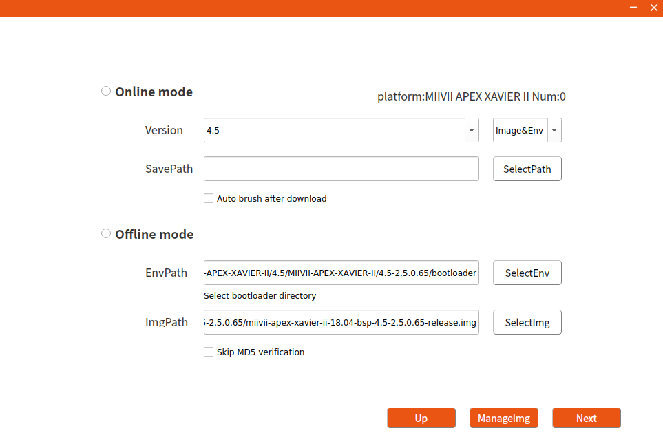
3.2.1.2 Off-line Mode Mirror Burning
- Click the "Offline mode" checkbox, select the downloaded brush environment and device image, and click "Next" to start burning directly.
3.2.2. Mirror Clone
- Enter the Miivii device into FORCE_Recovery mode according to the method of 3.1, and open the burning tool.
- Click the "Enter password" button ,enter the boot password of the burning host.
- Click "Clone" button,enter cloning operation.
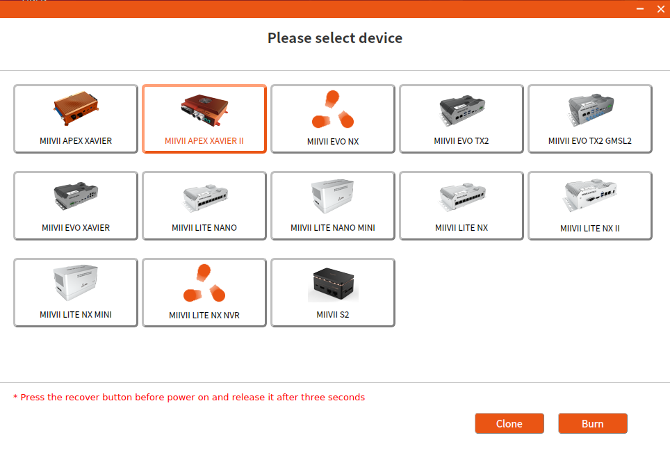
- Modify the path and name of the cloned file stored in the burning host, and click "Clone".
Note: Chinese or special characters are not allowed in the file storage path.
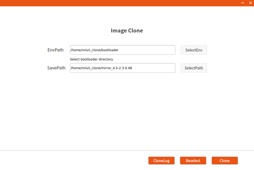
- Cloning usually takes more than 30 minutes to complete:
- After the clone is completed, the clone image and MD5 file will be generated. Please follow the steps in 3.2.1 to burn again.
Note: If you have any problems in the process of image burning and cloning, please contact Miivii after-sales mailbox for help: helpdesk@miivii.com.
Appendix 1. Self-check of Burning Problem
If you have any burning problems, please check yourself according to the following items first:
- Whether the PC boot password is entered in the upper left corner of the burning tool.
- Whether you have entered Recovery mode, which can be identified by lsusb command.
- Whether the quality of Micro USB and dual Type A cables is up to standard, and whether they are for charging.
- Whether the upper computer is a desktop or notebook computer with X86-64 architecture. (Currently, other devices such as servers, embedded devices and virtual machines are not supported)
- Whether the host computer system is Ubuntu Linux x64 v16.04 , v18.04 or v20.04 ( As of v1.6.0.8 , support Ubuntu20.04, "sudo apt-get install miivii-ftool " Upgrad version & View version )
- Check the disk format, the disk format of the burning host is recommended as EXT4.
- Whether the upper computer capacity is sufficient.
- The mirror burning tool storage path cannot contain Chinese characters or other special characters.
Appendix 2. Flash Tools Release Note
Product | Date | Version | Update content | Remark |
|---|---|---|---|---|
| MiiVii-FTool | 2022/08/16 | V1.6.0.8 | Add:MIIVII LITE TX2 NX II Add:MIIVII LITE TX2 NX MINI Add:MIIVII APEX AD10 Add:Supports Ubuntu20.04 Host OS Add:Add prompts of " The mirror clone supports only EMMC " Fixed: Less than 60 GB is displayed when the free disk space is greater than 2 TB | |
| MiiVii-FTool | 2022/06/29 | V1.5.0.2 |
| |
MiiVii-FTool | 2022/06/14 | V1.4.0.119 | Function Update:
| To ensure compatibility, the OS version will be checked when the software is started. V1.4.0.119 also supports only Ubuntu16.04 and Ubuntu18.04. Future versions will support more operating system versions. |
Instructions for using online system upgrade (OTA)
Summary
Online system upgrade, usually called OTA, is a software service provided by MIIVII for all MIIVII devices.
That is, the system firmware can be updated without brushing.
Starting from Jetpack 4.5, all MIIVII devices support OTA.
Usage Mode
Method 1 (recommended): use MIIVII SETTINGS for version upgrade and rollback; reference "Appendix 3 WEBSTTINGS".
- Open the browser on the device and enter http://127.0.0.1:3000, or enter http://<device ip>:3000 on the remote PC browser.
- Use the system login account to log in to the MIIVII SETTINGS;
- Select the system upgrade function and click "Check Upgrade" to check whether there is a new version.
Method 2: Use the command line to upgrade or upgrade the specified installation package.
Upgrade Using The Command Line
Execute the following command to update the source
sudo apt update
Execute the following command to upgrade the system.
sudo apt upgrade -y
Restart the system after the upgrade to ensure that the upgrade takes effect.
Specify The Upgrade Installation Package
Execute the following command to upgrade the specified installation package.(Take updating websettings 1.4.0 as an example.)
sudo apt install -y miivii-websettings=1.4.0
Appendix 3 WEBSETTINGS
MIIVII WEB SETTINGS Manual(JP 4.5 or later)
Introduction
MIIVII WEB SETTINGS is a graphical tool based on web,for device settings .
Provides such functions as system status detection, remote access, remote login and so on.
Access Method:
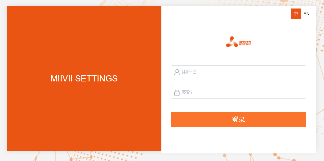
Method1- Access shortcut on local desktop:
- Double-click the desktop shortcut of “MIIVII WEBSETINGS” ,open the application of MIIVII WEBSETINGS
The login user must have root permission . The user without root permission cannot use it .
Default ID : nvidia Default PWD: nvidia
Method2- Access local browser:
- Open local browser
- Input http://127.0.0.1:3000
The login user must have root permission . The user without root permission cannot use it .
Default ID : nvidia Default PWD: nvidia
Method3- Access browser of client PC in same LAN:
- Open browser of client PC in same LAN
- Input “ The LAN IP of device + port number”,port number is 3000 . For example http://192.168.1.100:3000
The login user must have root permission . The user without root permission cannot use it .
Default ID : nvidia Default PWD: nvidia
Function Description
Switching between Chinese and English interface
In the upper right corner of the page ,click the switch button 
(Chinese/English switching is available from MWS V2.5.x and later versions)

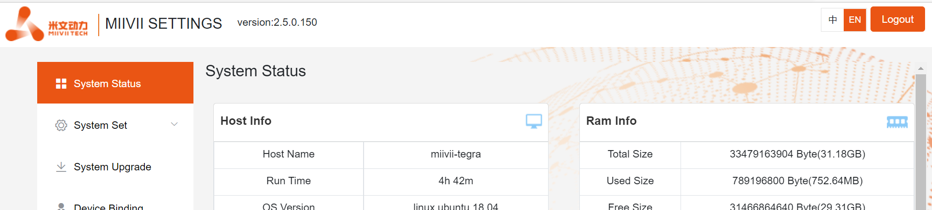
System Status
View basic information about the current system, such as CPU usage, memory usage, and storage usage.
- Click "System Status" on the left menu bar to enter the page.
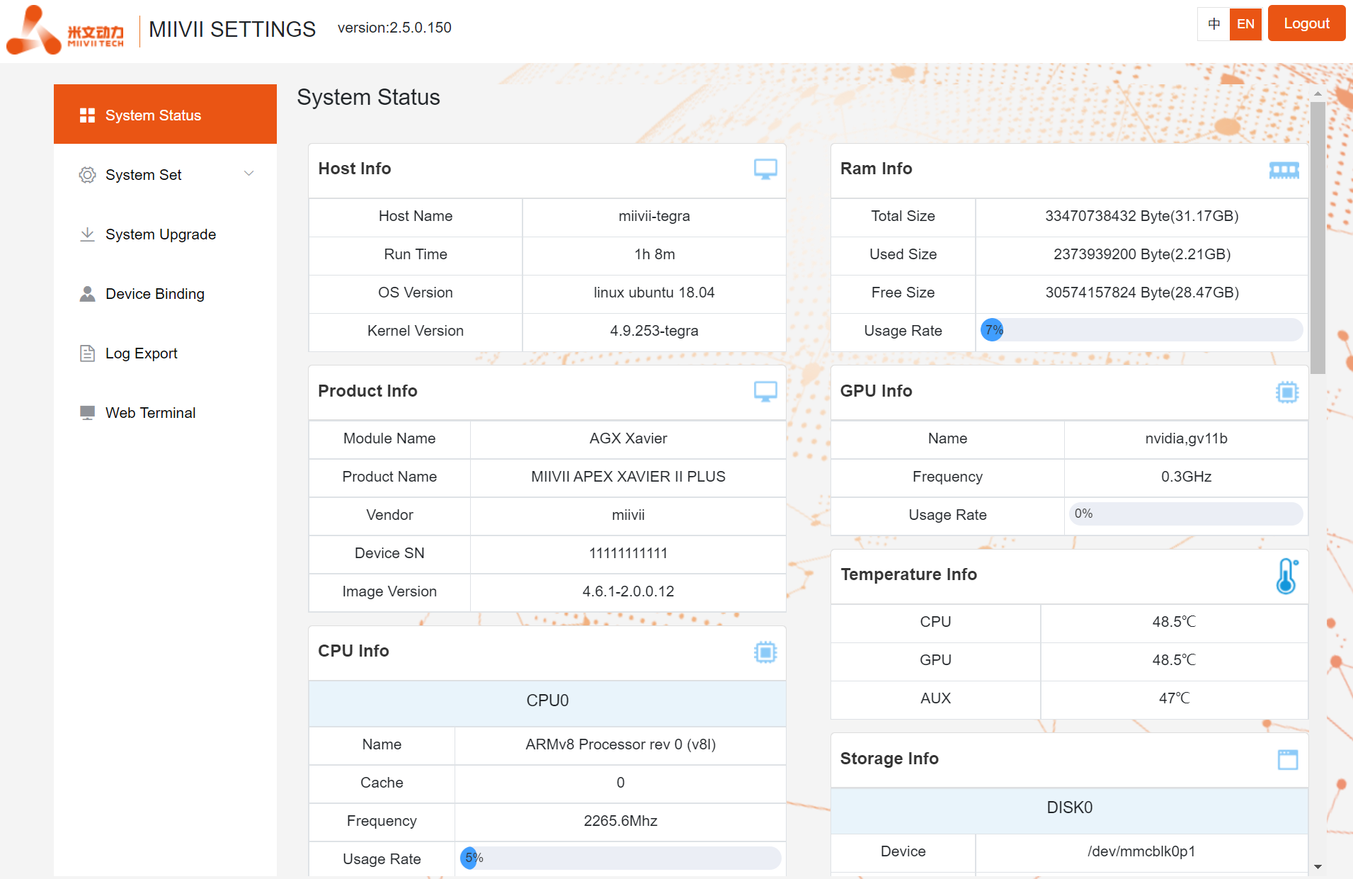
You can also view the system version on the CLI(For LAN access, use the "WEB Terminal" function):
cat /etc/miivii_release
APEX 4.2.2-1.5.0
System Settings
Set up basic system functions, such as system timing Settings,and so on.
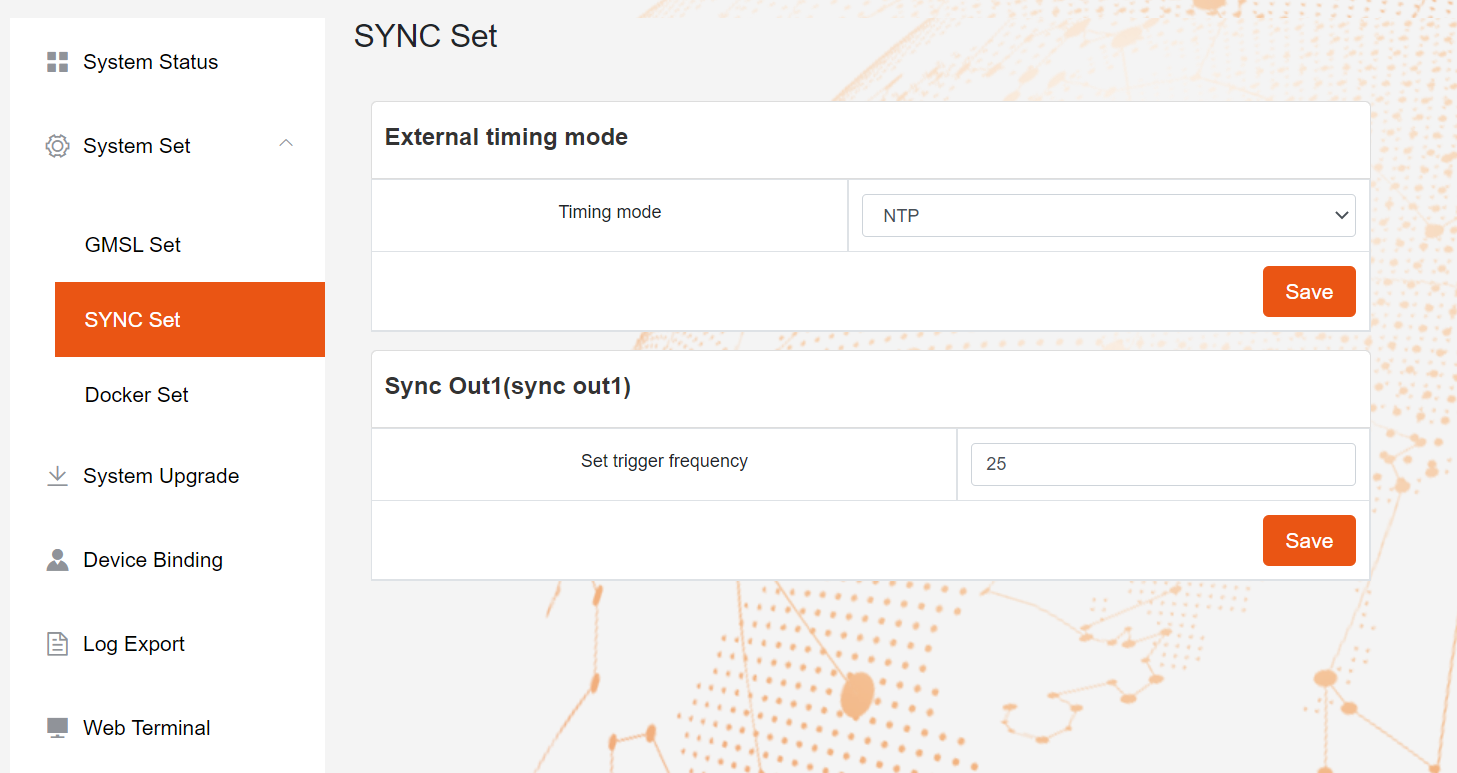
SyncSettings (system timing Settings)
Click the left menu bar "System Set - SYCN Set" to enter the page.
Choose external timing mode : NTP/GPS/NONE
- "NTP" is the default mode. NTP network timing mode:
- The device is connected to the network and timed by the NTP service. The device can be used as a synchronous source to time and synchronize the sensor.
- "GPS" is GPS external timing mode.:
- In this case, the device is connected to GPS and timed by GPS. The device can be used as a synchronization source to time and synchronize the sensor
- "None" is the asynchronous mode. In this case, the device is not timed but can be used as the synchronization source.
- "NTP" is the default mode. NTP network timing mode:
Set Sync out :
- Adjust the Sync out output frequency. Note that this is not the GMSL frequency.
- "Apex Xavier", "Apex Xavier II", "Apex Xavier II+" have the function of SYNC
- "EVO Xavier", "EVO Xavier II", "EVO TX2 GMSL2", "S2Pro" have the function of SYNC
- "EVO TX2" , "S2" don't have the function of SYNC
- "LIte xxxx" product series don't have the function of SYNC
Configuration file path:
/opt/miivii/config/sync/sync.cfg
- The timing mode is implemented by modifying the X value of "sync_type:X".
- 0: GPS external timing mode
- 1: NTP network timing mode
- 2: Asynchronous mode
cat /opt/miivii/config/sync/sync.cfg
sync_out_freq:25
sync_type:2
/*
note:
sync_out_freq---the frequency is 25 for sync out time
sync_type---0 is for GPS calibrate time
1 is for SYS calibrate time
2 can not calibrate time
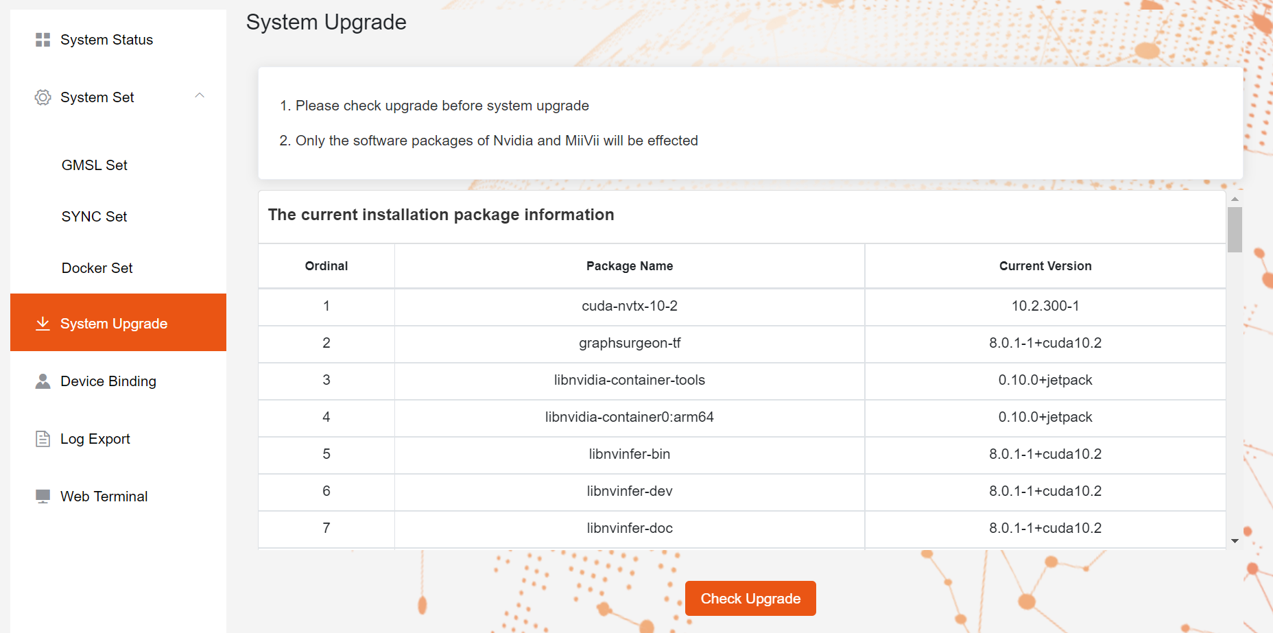
System Upgrade
MiiVii provides OTA upgrades to equipment systems.
Click the left menu bar "System Upgrade" to enter the page.
- Click "Check Upgrade" , If have new version , click ""
Device Binding
MiiVii provides the EdgeService cloud service. Enabling the cloud service requires binding devices.
Click the left menu bar "Device Binding" to enter the page.
- Bind the device as prompted. Use wechat to scan.

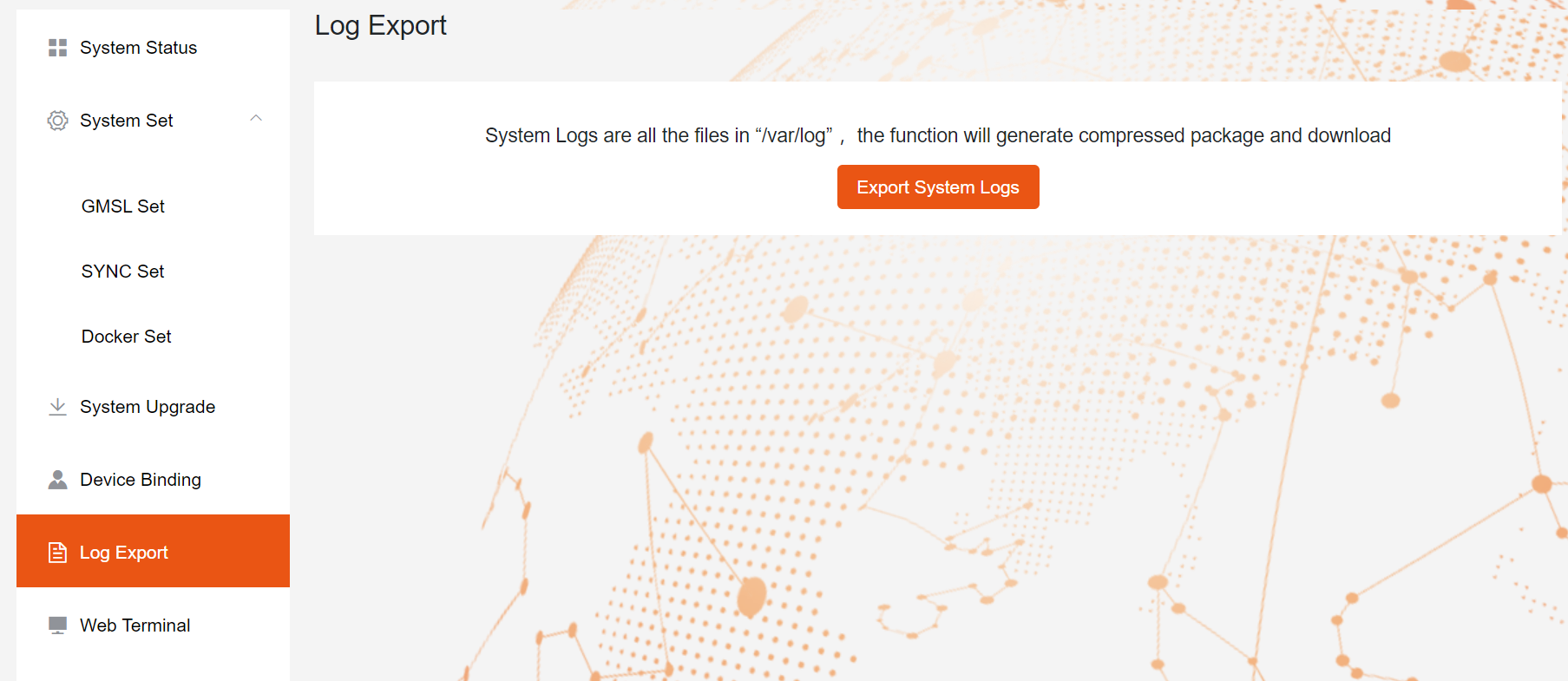
The log export
System run logs are stored in logs in /var/log/,The Log Export function allows you to package and download logs to a local PC.
Click the left menu bar "Log Export" to enter the page.
- Click "Export System Logs" to complete.
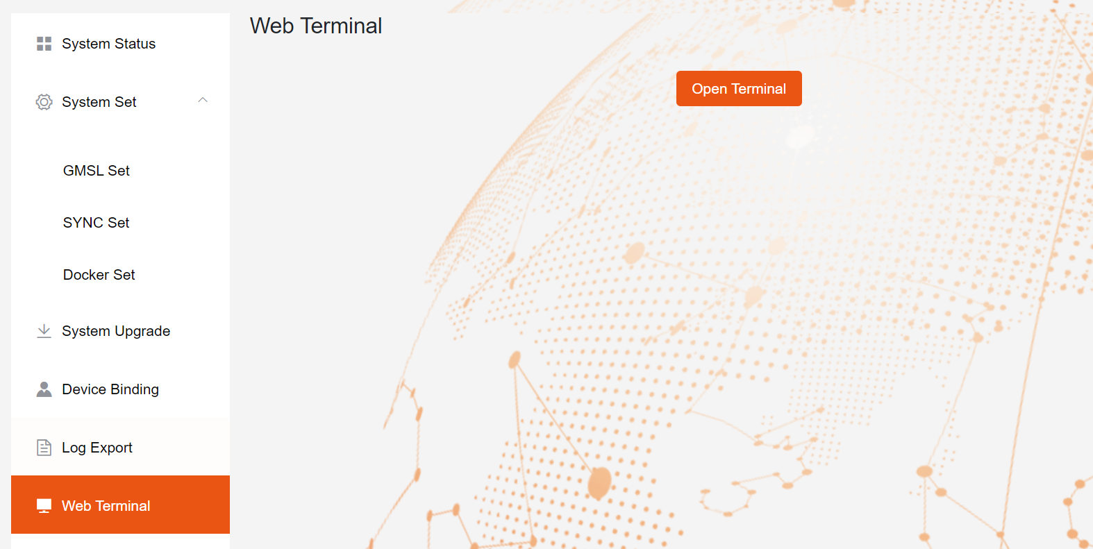
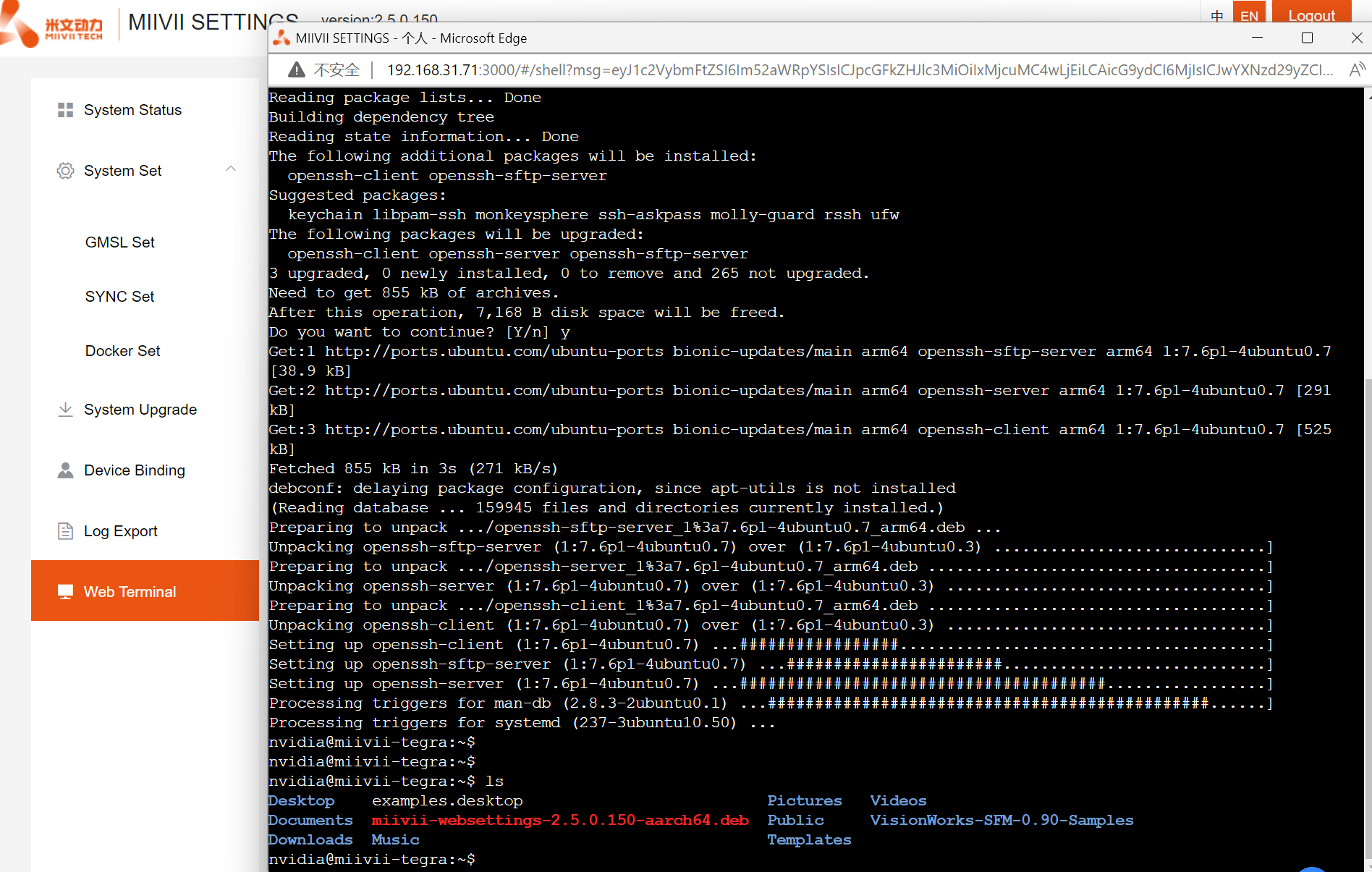
WEB Terminal
MiiVii Web Settings provides the remote terminal function through the WEB
Click "WEB Terminal" on the left menu bar to enter the page.
Click "Open terminal" to open the WEB terminal (as shown below)
Appendix 4 EVO Xavier II Release Note
| Product | Update Time | System Version | Update information | Note |
|---|---|---|---|---|
| MIIVII EVO XAVIER II | 2022-07-08 | 4.6.1-2.0.0.24 |
| |
| 2022-07-14 | 4.5-1.0.0.5 |
| ||