- Notice
- Interfaces
- General Setting
- Appendix
Please read manual carefully before install, operate, or transport MiiVii device.
Ensure that the correct power range is being used before powering the device.
Avoid hot plugging.
To properly turn off the power, please shut down the Ubuntu system first, and then cut off the power. Due to the particularity of the Ubuntu system, on the Nvidia developer kit, if the power is turned off when the startup is not completed, there will be a 0.03% probability of abnormality, which will cause the device to fail to start. Due to the use of the Ubuntu system, the same problem also exists on the Miivii device.
Do not use cables or connectors other than described in this manual.
Do not use MiiVii device near strong magnetic fields.
Backup your data before transportation or MiiVii device is idle.
Recommend to transport MiiVii device in its original packaging.
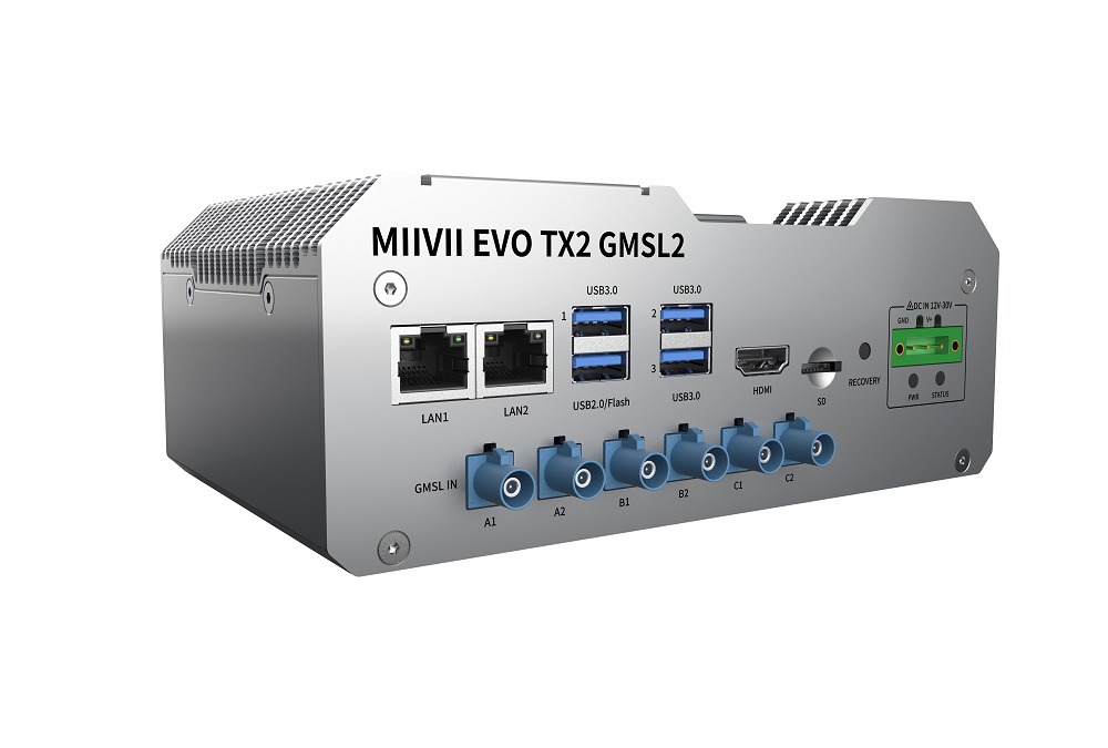
MiiVii EVO TX2 GMSL2 is an embedded edge AI platform designed for industrial application. It Supports NVIDIA® Jetson TX2, featuring over 1.3TFlops(FP16) for real-time inference. Thanks to MiiVii’s passive cooling design, EVO TX2 GMSL2 is capable of effectively dissipating the heat generated by the GPU, and guarantees system operation of up to 60°C ambient temperature.MiiVii EVO TX2 GMSL2 equipped with various I/O interface,especially 6*GMSL2 port. In addition, EVO TX2 GMSL2 also features massive expansion port to enhance accessibility.
Included in the Box
-EVO TX2 GMSL2 x 1
-Power cable x 1
-Fixed plate x 2
-Screws
-Quick start x 1
Specifications
Processor
| Processor | NVIDIA Jetson TX2 |
|---|---|
| CPU | Dual-core Denver 2 64-bit CPU and quad-core ARM A57 complex |
| GPU | 256 CUDA cores Pascal™ architecture |
| Memory | 8 GB 128-bit LPDDR4 |
| Storage | 32GB eMMC 5.1 |
I/O
| Interface | Quantity | Note | |
| Function KEY | Recovery Button | 1 | |
| Network | Ethernet | 2×Gigabit Port | 2 independent Gigabit Ethernet port RJ45 |
| Camera | Camera | 6×GMSL FAKRA Z TYPE | 10V Transmission distance up to 15 meters GMSL2,compatible with GMSL1 |
| Video output | HDMI | 1×HDMI 2.0 TYPE A | 5V 1A |
| USB | USB | 3×USB 3.0 TYPE A 1×USB 2.0 TYPE A | USB 5V, 1A USB 2.0 Flashing Port |
| I/O | UART | 2xRS232 1xRS485 | DB9 Terminal |
| CAN | 2 | Two CAN in One DB9 Terminal With CAN chip, terminal resistor 120Ω | |
| GPIO | 2 | DB9 Terminal | |
| SYNC IO | 1 | DB9 Terminal | |
| User Expansion | TF Socket | 1xTF Slot | MicroSD card supported |
| M.2 | 1×M.2 M Key | 2242 SIZE NVME SSD | |
| Mini PCle | 1 | For 4G or WiFi expansion | |
| Nano SIM Socket | 1 | For Nano SIM Card |
Power Supply
| Power Supply | Spec |
|---|---|
| Input Type | DC |
| Input Voltage | Wide input 12V-30V DC |
| Maximum Consumption | 15W |
Mechanical
| Mechanical | Spec |
|---|---|
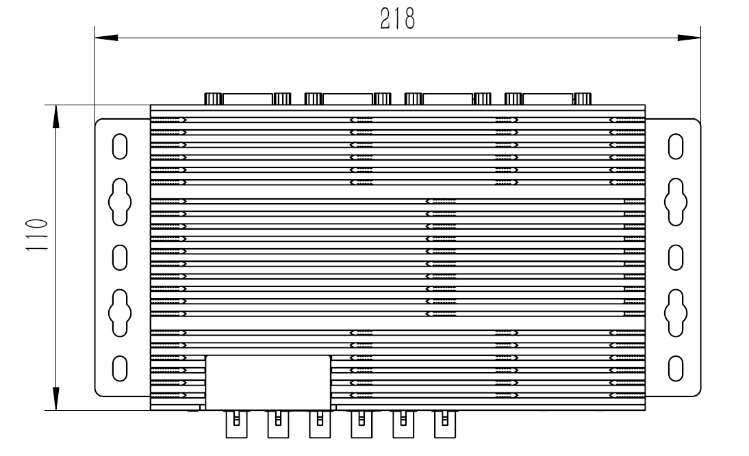
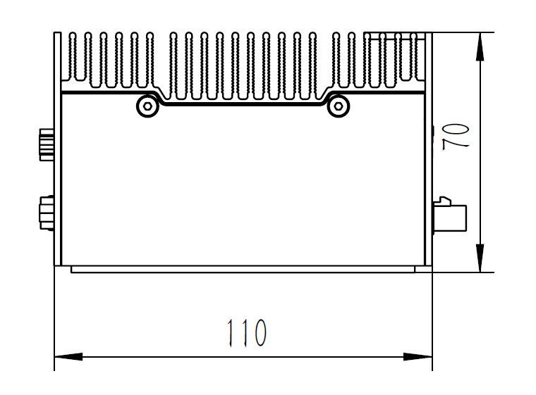
| Dimensions (W×H×D) | 178mm×55mm×110mm (I/O ports and mounting holes excluded) |
| Weight | 1.2Kg |
Environmental
| Environmental | Spec |
|---|---|
| Operating Temperature | -20℃-60℃, 0.2~0.3m/s air flow1 |
| Storage Temperature | -25℃-80℃ |
| Storage Humidity | 10%-90% non-condensing |
| Vibration | 5gn,10Hz~150Hz,3 Axis2 |
| Protection | IP4X |
| ESD | Touch 6KV, Air 8KV |
| TVS | 500V |
Certification
| Certification | Status |
|---|---|
| CCC, CE, FCC, RoHS, SRRC | Processing |
[1] According to GB/T 2423-2008 Working frequency is subject to change after temperature reaches 60℃
[2]
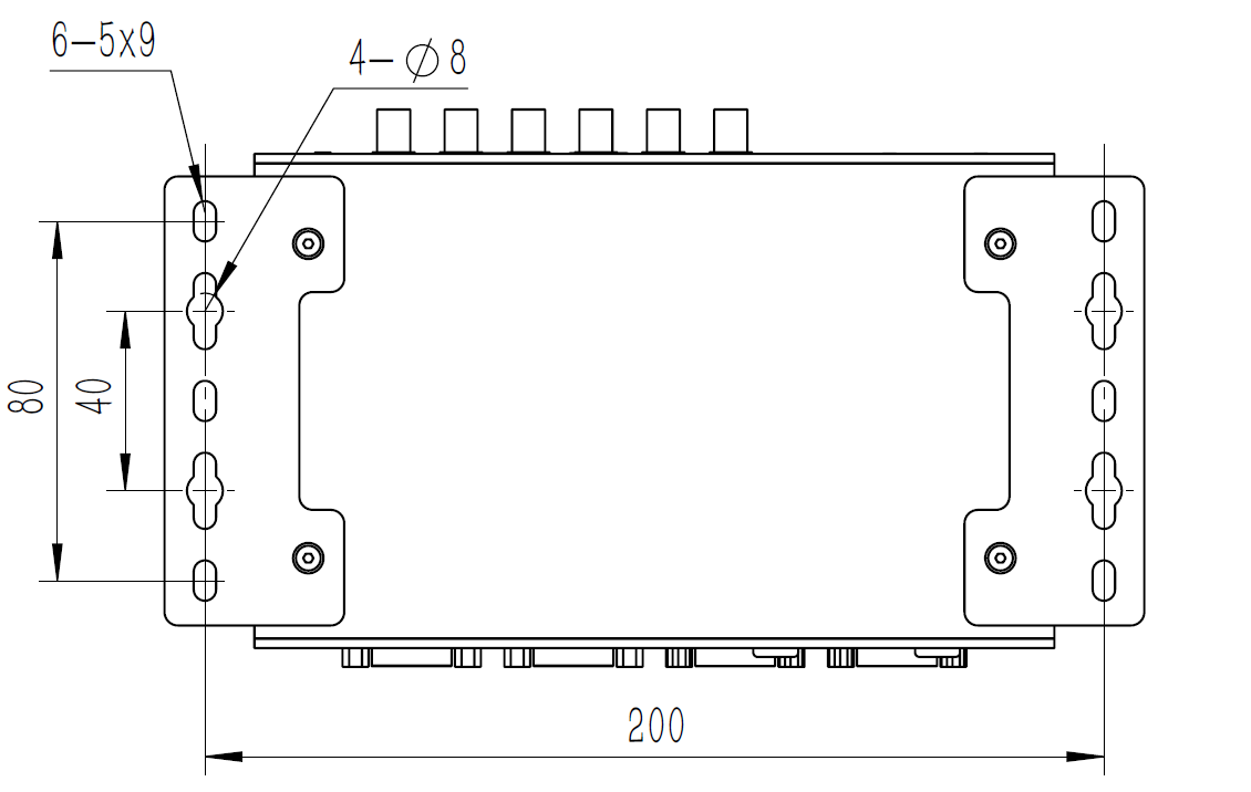
Dimensions and mounting hole position as below:
| Up view(Unit:mm) |
|---|
|
| Front view(Unit:mm) |
|
| Left view(Unit:mm) |
|
| Mounting Hole(Unit:mm) |
|

Support
MiiVii is glad to help you with any questions you may have about our product, or about the use of the technology for your application. The fastest way is sending us an email: . Or you could visit our developer forum: http://forum.miivii.com for solutions.
Warranties
Warranty period: One year from the date of delivery.
Warranty content: MiiVii warrants the product manufactured by us to be free from defects in material and workmanship during warranty period. Please contact helpdesk@miivii.com for return material authorization (RMA) prior to returning any items for repair or exchange. The product must be returned in its original packaging to prevent damage during shipping. Before returning any product for repair, it is recommended to back up your data and delete any confidential or personal data.
Interfaces
Interfaces
Front panel
|
|---|
| Figure EVO TX2 GMSL2 Front view |
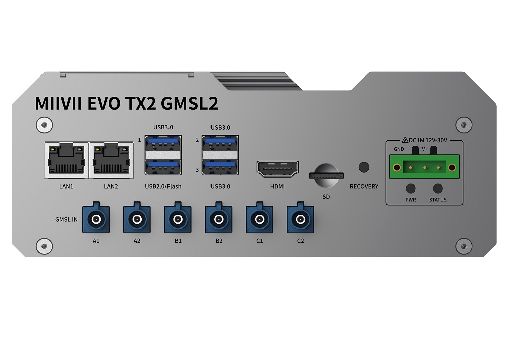
| Interface | Name | Description |
|---|---|---|
| LAN_1,LAN_2 | Gigabit Ethernet | 2 independent Gigabit Ethernet port |
| USB | 3×USB 3.0 TYPE A 1×USB 2.0 TYPE A | USB 2.0 Flashing Port 5V 1A |
| GMSL | GMSL in | Support 6 GMSL2 cameras(10v) GMSL2 compatible with GMSL1 |
| HDMI | HDMI | HDMI 2.0 TYPE A 5V 1A |
| SD | TF Slot | MicroSD card supported 3.3V 1A |
| RECOVERY | Recovery Button | Inter Recovery mode while pressing |
| DC IN | Power interfaceA | Wide input 12V-30V DC |
| PWR | Carrier board status indicator | Carrier board power on: solid yellow Carrier board system on: solid white Carrier board system error: solid red |
| STATUS | System status indicator | System on: solid blue System off: solid red |
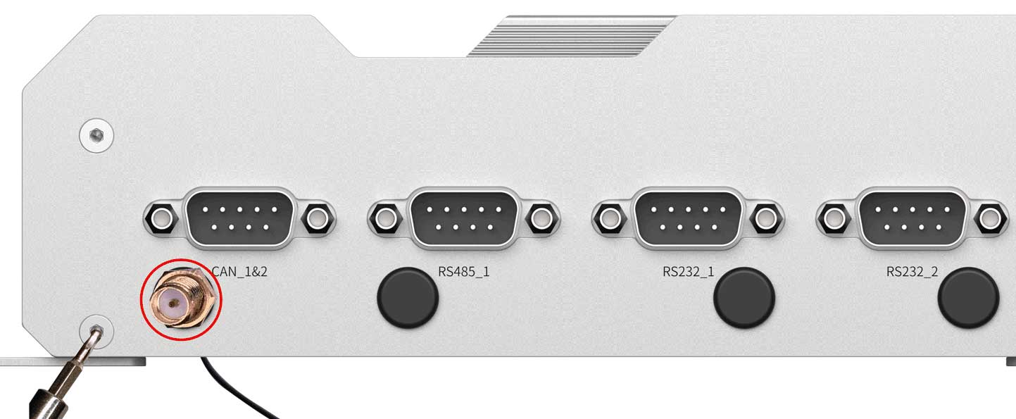
Back Panel
|
|---|
| Figure EVO TX2 GMSL2 Back Panel |

| Interface | Name | Description |
|---|---|---|
| CAN_1&2 | CAN port 1 and 2 | Include 2 CAN signal 7.5V Max@48mA Max With CAN chip, terminal resistor 120Ω |
| RS485_1 | RS485 port 1 | 2.0VDC Min, 1mA Max |
| RS232_1 | RS232 port 1 | Logic1: -3V~-12V,Logic0: 3V~12V,1.6mA Max |
| RS232_2 | RS232 port 2 | Logic1: -3V~-12V,Logic0: 3V~12V,1.6mA Max |
| GPIO_1&2 | GPIO port | 2×GPIO_IN High 1V-12V, Low 0V-0.8V 2×GPIO_OUT 3.3V |
| Sync IO | Sync IO | 1×SYNC_IN 1×SYNC_OUT 1×PPS |
CAN Pin Assignment
|
|---|
| Figure CAN_1&2 Pin Assignment |

| Port Name | Pin | Signal | Description |
| CAN_1&2 | 1 | TX2_CAN1_L | TX2_CAN_1 L |
| 2 | TX2_CAN0_L | TX2_CAN_0 L | |
| 3 | GND | GND | |
| 4-5 | NC | NC | |
| 6 | GND | GND | |
| 7 | TX2_CAN0_H | TX2_CAN_0 H | |
| 8 | TX2_CAN1_H | TX2_CAN_1 H | |
| 9 | NC | NC |
RS485 Pin Assignment
|
|---|
| Figure RS485 Pin Assignment |
| Port Name | Pin | Signal | Description |
| RS485_1 | 1 | NC | NC |
| 2 | RS_485A | RS485_1 A | |
| 3 | RS_485B | RS485_1 B | |
| 4 | NC | NC | |
| 5 | GND | GND | |
| 6-9 | NC | NC |
RS232 Pin Assignment
|
|---|
| Figure RS232 Pin Assignment |
| Port Name | Pin | Signal | Description |
| RS232_1 | 1 | NC | NC |
| 2 | USB_UAR8_RXD | RS232_1 recieve | |
| 3 | USB_UAR8_TXD | RS232_1 transmit | |
| 4 | NC | NC | |
| 5 | GND | GND | |
| 6-9 | NC | NC | |
| RS232_2 | 1 | NC | NC |
| 2 | USB_UART9_RXD | RS232_2 recieve | |
| 3 | USB_UART9_TXD | RS232_2 transmit | |
| 4 | NC | NC | |
| 5 | GND | GND | |
| 6-9 | NC | NC |
UART Port Device Node
Relation of UART Port and device node as follow:
| UART Port Name | Device Node |
|---|---|
| RS485_1 | ttyUART_485_1 |
| RS232_1 | ttyUART_232_1 |
| RS232_2 | ttyUART_232_2 |
GPIO Pin Assignment
|
|---|
| Figure GPIO Pin Assignment |
| Port Name | DB9 Pin Number | Signal | Description |
| GPIO_D | 1 | GPIO3_PY.00_3V3 | GPIO IN |
| GPIO_E | 2 | GPIO3_PY.06_3V3 | GPIO IN |
| GPIO_B | 3 | GPIO3_PB.04_3V3 | GPIO OUT |
| GPIO_C | 4 | GPIO3_PI.05_3V3 | GPIO OUT |
| NC | 5,9 | NC | NC |
| GND | 6-8 | GND | GND |
GPIO Port
| GPIO Name | GPIO Default | GPIO Export Value |
|---|---|---|
| GPIO_B | GPIO_OUT | 332 |
| GPIO_C | GPIO_OUT | 389 |
| GPIO_D | GPIO_IN | 480 |
| GPIO_E | GPIO_IN | 486 |
SYNC_IO Port
|
|---|
| Figure SYNC_IO pin Assignment |
| Port Name | DB9 Pin | Definition | Description |
| PPS Sync | 2 | PPSA_UART_RX | PPSA_UART(TTL/232) Signal:RX |
| 3 | PPSA_UART_TX | PPSA_UART(TTL/232) Signal:TX | |
| 5 | GND | GND | |
| 6 | AO_DMIC_IN_3V3 | PPS_A Pluse signal 3.3V | |
| GND | 1 | GND | GND |
| Sync out | 9 | GPIO_PW5_3V3 | Sync out Signal |
| Sync in | 7 | GPIO_PAA02_3V3 | Sync in Signal |
Debug Port
The Debug Port(RS232) of EVO TX2 GMSL2 located on the back of PCBA, please refer to the folowing figure. PIN 8 RX, PIN 10 TX
|
|---|
| Figure Debug Port |
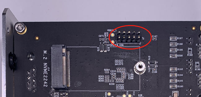
| Pin | Signal | Description |
|---|---|---|
| 6 | GND | GND |
| 8 | DGB_UART0_RX_232 | Debug Port recieve signal |
| 10 | DGB_UART0_TX_232 |
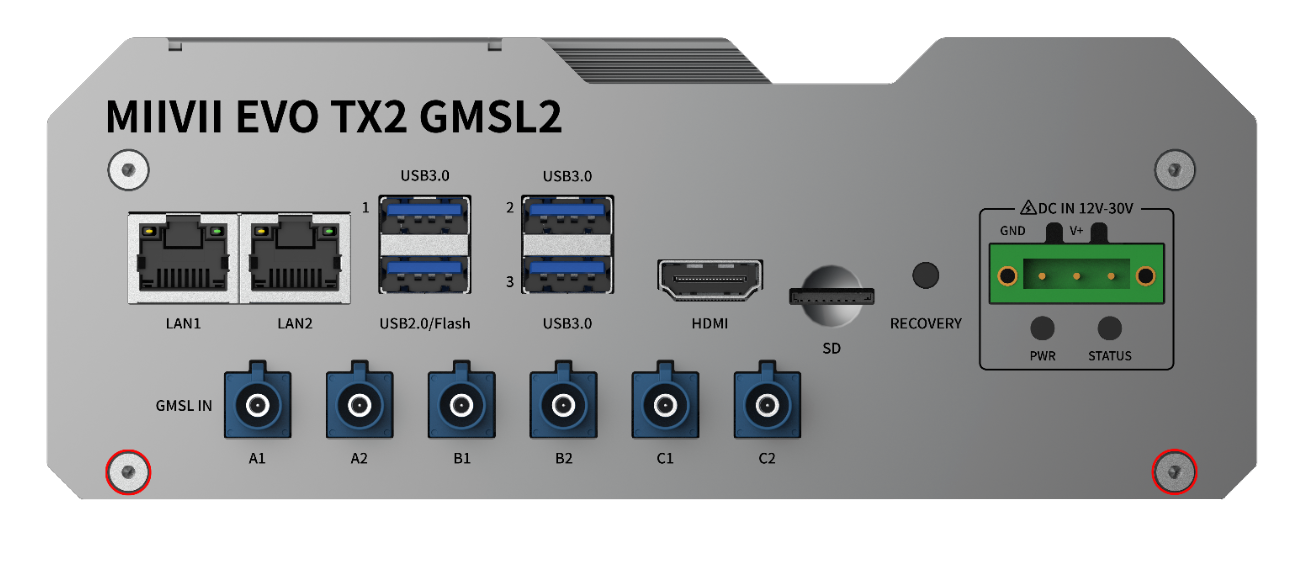
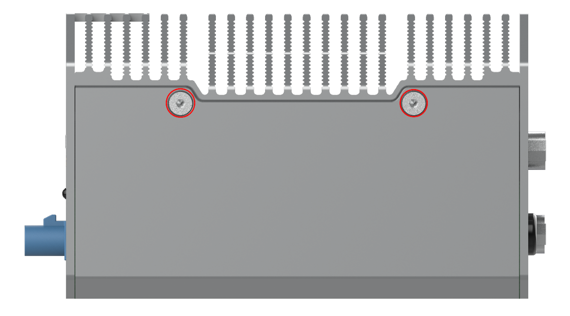
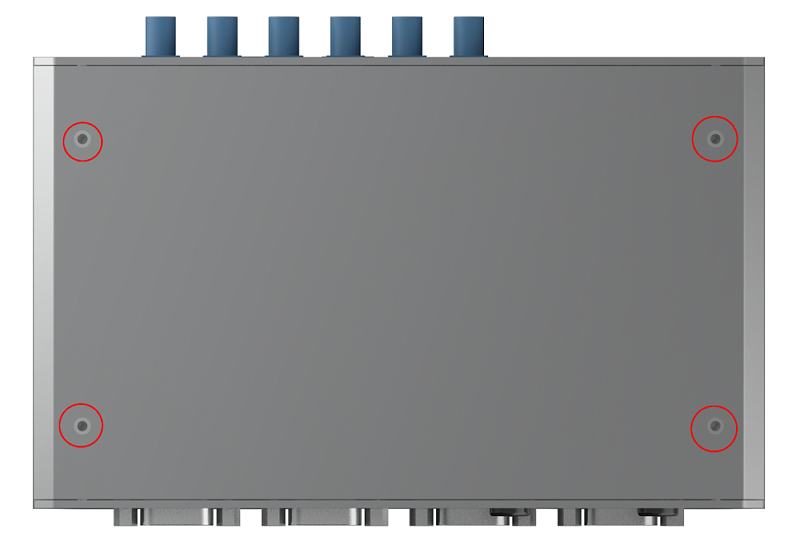
Expansion device installation
EVO TX2 GMSL2 provides M.2 M Key, mini PCIe port for storage and communication expansion
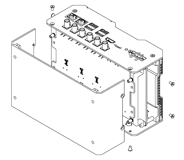
Unscrew 8 screws and take off bottom cover of EVO TX2 GMSL2 while installation expansion device:
|
|---|
| Figure EVO TX2 GMSL2 Screw Position1 |
|
|---|
| Figure EVO TX2 GMSL2 Screw Position2 |

|
|---|
| Figure EVO TX2 GMSL2 Screw Position3 |
|
|---|
| Figure Remove Bottom Cover |
Expansion port position as follow::
|
|---|
| Figure Expansion Port Position |
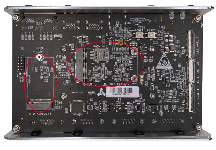
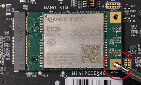
Install expansion device based on demand. Please note that if you need 4G module, insert nano SIM card into nano SIM socket before install 4G module.
|
|---|
| Figure Moudle |
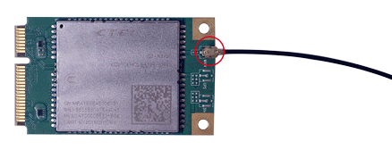
Please install WiFi/4G antenna to ensure signal stability.
|
|---|
| Figure Antenna Installation1 |
|
| Figure Antenna Installation2 |
Please refer to the first step, and restore EVO TX2 GMSL2 after install expansion device.
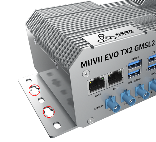
Fixed Plate installation
Please install fixed plate first if you need to securing EVO TX2 on another system.
|
|---|
| Figure Fixed Plate1 |
|
|---|
| Figure Fixed Plate2 |
General Setting
General Setting
System
MiiVii device use Ubuntu system. Default username: nvidia default password: nvidia
System Image and Flashing Tool
Please visit MiiVii developer forum: http://forum.miivii.com/ for flash tool and system image.
Power on
Connect an external HDMI display to MiiVii's HDMI port.
Connect a USB keyboard and mouse.
Connect the included AC adapter to power socket. Plug AC adapter into an appropriately rated electrical outlet.
|
|---|
| Figure Startup |

Power off: Use the following command in terminal.
For MiiVii device with entity PWR button, you can also press and hold PWR button.
sudo poweroff
Reset: Use the following command in terminal.
sudo reboot
MiiVii Setting
MiiVii Device provides a setting program called MiiVii Setting. You can get access to basic information and settings through MiiVii Setting. Click the icon on upper right corner。In addition, these settings can be set through code, please refer to the section after MiiVii Setting introduction.
|
|---|
| Figure Version Info |

You can set up GMSL camera here. MiiVii Device Apex has two groups of GMSL camera GMSL_A and GMSL_B, while MiiVii Device S2Pro has only one group GMSL_A.
|
|---|
| Figure Set up GMSL Camera |

You can set up Sync mode here:
|
|---|
| Figure Set Synchronization Mode |
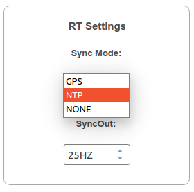
Default setting is NTP mode. MiiVii Device accept NTP service while set to this mode.
MiiVii Device accept GPS synchronization while set to GPS mode.
MiiVii Device cannot be synchronized but can synchronize other sensors while set to None mode.
You can also set Sync out frequency here, please note it is not GMSL frequency.
Finish setting and exit
|
|---|
| Figure Finish setting |

You can also check software version through code
cat /etc/miivii_release
APEX 4.2.2-1.5.0
Set up GMSL Camera
When accessing GMSL camera for the first time and changing GMSL camera model, you need to change the configuration file and restart the device.Configuration file path:/opt/miivii/config/gmsl_camera/camera.cfg MVGCB-001A :Entron MVGCB-002A: Calmcar MVGCB-003A:Adayo MVGCB-006A:Sensing The default configuration of GMSL_A and GMSL_B are both MVGCB-001A.
Set up synchronization Mode and Sync out frequency Synchronization Mode and Sync out frequency settings need to modify the configuration file and restart the device.Configuration file path:/opt/miivii/config/sync/sync.cfg Synchronization Mode is achieved by modifying the X value of "sync_type:X". 0:GPS mode 1:NTP mode 2:None mode Sync out frequency is achieved by modifying the XX value of "sync_out_freq:XX". Only integers are supported.\
cat /opt/miivii/config/sync/sync.cfg
sync_out_freq:25
sync_type:2
/*
note:
sync_out_freq---the frequency is 25 for sync out time
sync_type---0 is for GPS calibrate time
1 is for SYS calibrate time
2 can not calibrate time
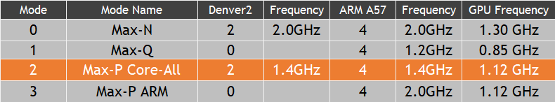
MiiVii device has several power modes. You can set up power mode through the green NVIDIA icon on the upper right corner.
|
|---|
| Figure Power mode Icon |

For MiiVii device equipped with NVIDIA Jetson TX2, the following table shows details of each power mode. The default mode is 2.
You can also set up through code:
#check current mode
sudo nvpmodel -q verbose
# set to a certain mode
sudo nvpmodel -m [MODE ID]
#achieve best performance of current mode
sudo jetson_clocks
#check more info
sudo jetson_clocks --show
GPIO
Please change the code in <> to your GPIO export value
#switch to root
sudo su -
#set GPIO to high
echo 1 > /sys/class/gpio/<gpio339>/vlaue
#set GPIO to low
echo 0 > /sys/class/gpio/<gpio339>/vlaue
For auto config, write above commands to file /etc/rc.local.
Note: Description of GPIO external connection
DO is on/off output (on/off output is no output voltage, control output low voltage, pin grounding in normal time, control output high voltage, pin neither output high level nor low level, high resistance state.If the external pull-up resistor is connected, the voltage will be drawn to the power supply voltage of the pull-up resistor at the time of high output voltage.)
Set to high voltage, DO foot and external voltage are the same (0V~40V); Set to low level, DO feet for the ground.
UART
Open device node in /dev/. Then use stty command to set parameters. See stty command manual for details, please change the code in <> to your UART device node.
#config UART
$ sudo stty -F /dev/<ttyTHS1> speed 115200 cs8 -parenb -cstopb -echo
#send data through UART
$ sudo echo “miivii tty debug” > /dev/<ttyTHS1>
#receive data from UART
$ sudo cat /dev/<ttyTHS1>
Use GPS To Give Time To The Device
Advantages of GPS timing function: The device obtains local standard time signal from GPS satellite through GPS device, so as to accurately locate the device time
GPS Support Model
The serial port supports modifying baud rate. The default baud rate is 9600 GPS brand supported: all GPS devices that conform to GPRMC data standard format output and must have PPS second pulse output
Connection Mode
Refer to the "Interface Description" in the manual.
Timing Function Configuration
When the GPS is connected for the first time, the system configuration should be conducted in MiiVii Setting configuration software. Configure the Sync Mode option to GPS Mode and restart the system.Please refer to the section of "MiiVii Setting" for specific methods.
Check Whether The Timing Was Successful
Modify the system time, enter the command
sudo date -s "2018-10-1"
Wait for 2~3s, check the current time, and enter the command
data
If the display time is: "2018-10-1", it means the timing failed If the display time is: "current time", the timing is successful
Troubleshooting
If the timing fails, fault troubleshooting shall be carried out
1. Check If The GPS Has Output
Type the command
cat /dev/ttyTHS1
The terminal receives output with a GPRMC field, such as: GPRMC,014600.00,A,2237.496474,N,11356.089515,E,0.0,225.5,310518,2.3,W,A*23
2. Check The OUTPUT of THE GPS PPS Signal
Type the command
hexdump /dev/miivii-sync-in-a
The terminal has hexadecimal data output, such as: 0000400 02fe 9f40 490e 562d 1647 004e 0000 0000
3. Identify Methods
If the above "1"&"2" has no output, indicating that the GPS is not working properly, you can put the GPS out of the window or go outside for testing, or change the GPS for testing
If the output of "1"&"2" is normal, check whether the MiiVii Setting configuration is in GPS mode. If not, change the mode and restart it
After the above operation, GPS timing is still unsuccessful, enter the command
hexdump /dev/miivii-sync-out
The terminal has hexadecimal data output, such as: 0000400 02fe 9f40 490e 562d 1647 004e 0000 0000
If there is no data output, it may be that there is no matching brush tool and mirror brush. It is recommended to check the mirror and the brush tool to re-brush
If there is data output, it may be a hardware problem,it is recommended to contact after-sales maintenance treatment
CAN
Please check cansend.c and candump.c from https://github.com/linux-can/can-utils for instructions.
Test command:
sudo modprobe can
sudo modprobe can_raw
sudo modprobe mttcan
sudo ip link set can0 type can bitrate 500000 berr-reporting on loopback off
sudo ip link set up can0
sudo cansend can0 123#abcdabcd
sudo candump can0
sudo ip -details -statistics link show can0
sudo ifconfig can0 down
CAN fd:
sudo modprobe can
sudo modprobe can_raw
sudo modprobe mttcan
sudo ip link set can0 type can bitrate 500000 dbitrate 2000000 berr-reporting on fd on
sudo ip link set up can0
sudo cansend can0 213##011
SSD Setting
#check ssd information: sudo fdisk -lu
|
|---|
| Figure SSD Information |

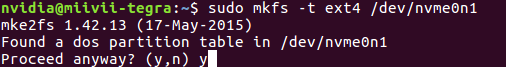
#Format SSD: sudo mkfs -t ext4 /dev/nvme0n1
|
|---|
| Figure Formatting SSD |
#Check UUID: sudo blkid /dev/nvme0n1
|
|---|
| Figure SSD UUID |

Setting method of automatic mounting SSD: Create a systemd service in the /etc/systemd/system path to automatically mount the SSD when booting, such as: miivii_mount_ssd.service
#Create miivii_mount_ssd.service
vim miivii_mount_ssd.service
[Unit]
Description=MIIVII specific script
After=udev.service

[Service]
ExecStart=/etc/systemd/miivii_mount_ssd.sh

[Install]
WantedBy=multi-user.target
Create a script in the /etc/systemd/ path to mount the SSD, such as: miivii_mount_ssd.sh
#Create miivii_mount_ssd.sh
vim miivii_mount_ssd.sh
#!/bin/bash
mount -o rw /dev/nvme0n1 /home/nvidia/workspace
change mode for this script
sudo chmod +x miivii_mount_ssd.sh
Set the mounted SSD service to start at boot
sudo systemctl enable miivii_mount_ssd.service
WiFi Setting
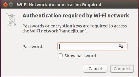
MiiVii S2, S2Pro and EVO TX2 ,EVO TX2 GMSL2 has WiFi function.While Apex Xavier MiiVii EVO Xavier, Lite NX and Lite Nano provides WiFi function via a expansion module. Please refer to the information in [Expansion] to intall WiFi module. Click the network icon in upper-right corner of the desktop. Find the name of your WiFi network and click on it. Enter your password and click ‘Connect’.
|
|---|
| Figure WiFi Connection |
4G Setting
4G module is not included in MiiVii device package. Please refer to the information in [Expansion] to intall 4G module. Instructions for 4G module configuration are shown as below, using QUECTEL EM05 as an example. EM05 4G driver is included in MiiVii system. This SIM card could be detected automatically. There should be 4 devices under /dev/ttyUSB0~/dev/ttyUSB3.
Users need to choose their own 4G LTE SIM card(note that mobile phone sim card and IOT sim card is supported, but IOT sim card is hardware-binding, please consult your carrier for more information ). Before getting started, please insert SIM card into sim socket.
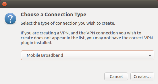
Click the network icon in upper-right corner of the desktop. Find 'Edit Connections', then click 'add'.

Change connection type to 'Mobile Broadband'
Next

Change country to 'China'. Then choose network provider.
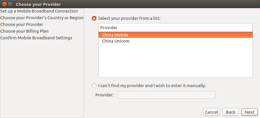
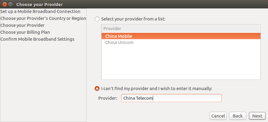
If your network provider is not included in the list, then enter it manually.
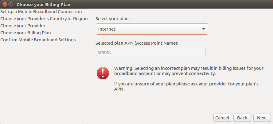
Choose your Plan
China Mobile choose 'Internet',China Unicom and China Telecom choose default
APN settings: China Mobile: cmnet; China Unicom: 3gnet; China Telecom: ctnet
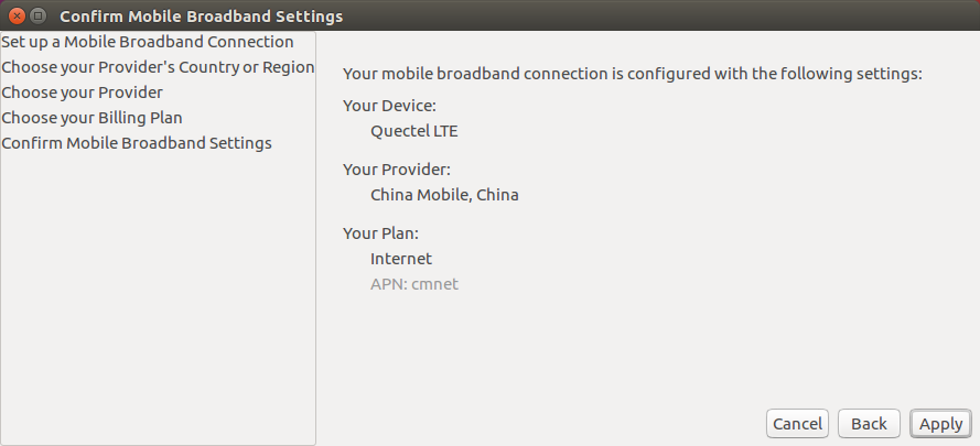
Check entire settings, then click 'Apply'
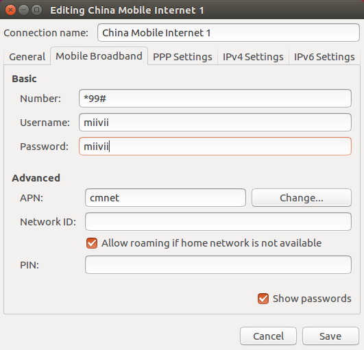
Enter username and password, click 'save'
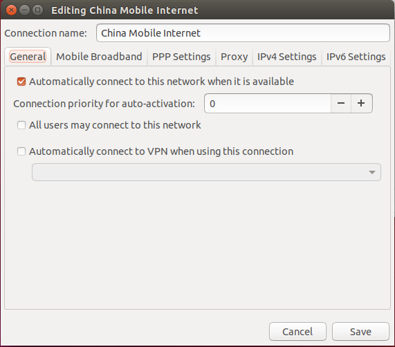
Click the network icon in upper-right corner of the desktop. Then connect to your network. If you need auto connection, please edit Network connections:
Select 'General', then check 'Automatically connect to this network when it is available'
Reset MiiVii device, you can automatically connect to 4G network
Sync Introduction
Apex Xavier provides 3 ways to synchronize sensor input data: PPS, Sync in and Sync out. Synchronization error is within 1μs. (Error estimation method is attached to the end of this section)
|
|---|
| Figure Sync Fearure Schematic |

Sync Function
PPS Sync Method
MiiVii device generates PPS(Pulse width: 50ms)1. The NMEA GPRMC message is sent through PPS port. NMEA message example:
$GPRMC,060249.000,A,3949.63046,N,11616.48565,E,0.296,,291118,,,A*4d
[1] For the hardware connection method of the PPS, please refer to the "PPS Ports and Pin Assignments" section in the "I/O Cable"
'060249.000' represents 'Time of fix 06:02:49 UTC'. Receiving PPS signal and GPRMC message, sensors which support PPS synchronization, could synchronize their internal clock with system time. Together with the timestamp, sensor data is sent to MiiVii device, so that Apex Xavier receives the data acquisition time.
|
|---|
| Figure PPS Sync Method Schematic |

Synchronization verification (RS-LiDar-16 sensor):
When the sensor connects with Apex Xavier using only data wire, device ROS Node sends hardware timestamp to the system, which is determined by sensor’s internal clock. As shown below, there is a big difference between hardware timestamp and system time.
|
|---|
| Figure Comparison of Lidar Time and ROS time without Synchronization |

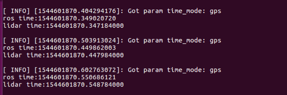
After connecting the sensor with MiiVii device's PPS_SYNC and PPS_TX pin, the sensor’s internal clock is synchronized with system time. Comparing the hardware timestamp and system time, when the difference is less than 100ms, it means PPS synchronization is functional.
|
|---|
| Figure Comparison of Lidar Time and ROS time after Synchronization |
Sync out Method
MiiVii device could generate one 1-30Hz signal (Pulse width: 5ms) through its sync-out pin2. This signal is received by sensors as trigger signal for data acquisition. Meanwhile, MiiVii device records the moment of this signal’s rising edge. After data acquisition, MiiVii device associates received data with the trigger signal’s rising edge moment as data timestamp. Thus, MiiVii device system obtains data acquisition time.
[2] For the hardware connection method of the Sync out, please refer to the "SYNC Ports and Pin Assignments" section in the "I/O Cable"
|
|---|
| Figure Sync out Method Schematic (25Hz) |

Also, MiiVii device provides sync-out feature for GMSL interface. See GMSL Camera Section for details.
Synchronization Verification
Set the sensor to external sync configuration. By recording ROS bags, check whether the sensor trigger signal equals to your setting or not. If the difference is within 1Hz, it means sync-out method is functional.
Sync in Method
Sensors with sync-in mode could generate a signal at the beginning of data acquisition3. MiiVii device receives this signal and records its rising edge moment. After data acquisition, MiiVii device associates received data with the signal’s rising edge moment as data timestamp. Thus, MiiVii device system obtains data acquisition time.
[3] For the hardware connection method of the Sync in, please refer to the "SYNC Ports and Pin Assignments" section in the "I/O Cable"
|
|---|
| Figure Sync in Method Schematic (10Hz) |

Synchronization Verification:
Print the signal’s timestamp received by SYNC_IN pin. Compare this timestamp with system time of frame received (ros::time::now). If the difference is less than 100 ms, it means sync-in method is functional.
Synchronization error estimation
Measure PPS signal duration with oscilloscope
|
|---|
| Figure PPS Signal Duration |
| Theoretical Value(μs) | Measurement Result(μs) | Error(μs) | |
|---|---|---|---|
| PPS | 1000000 | 999999.4 | 0.6 |
Measure sync-out signal duration with oscilloscope
|
|---|
| Figure Sync-out Signal Duration (10Hz) |
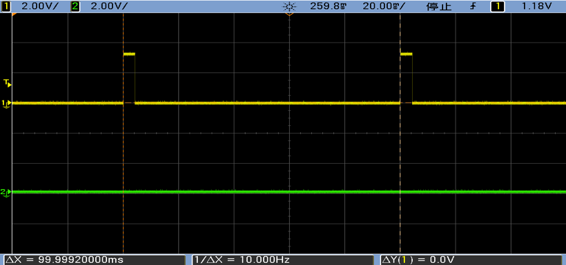
| Theoretical Value(μs) | Measured Value(μs) | Error(μs) | |
|---|---|---|---|
| Sync out | 100000 | 99999.2 | 0.8 |
Evaluate synchronization feature by measuring timestamp jitter
Sample code to calculate timestamp jitter
MiiVii device provides sample code for users to evaluate the synchronization feature.
#navigate to the following directory
cd /opt/miivii/feature/sync_test/bin
#evaluate sync-out method performance
./sync_out_test
#evaluate sync-in method performance
./sync_in_test
#evaluate pps synchronization method performance
./pps_test
Sync out jitter measurement
Sample code(sync_out_test) could run real-time analytics on the received timestamp. Time interval, frequency, max deviation and standard deviation are printed out.
|
|---|
| Figure Sync out Test Result |

Sync in jitter measurement
Connect an external signal with fixed frequency to MiiVii device SYNC_IN pin. Run sample code (sync_in_test) for real-time analytics on the received timestamp.
MiiVii device's SYNC_OUT pin could be used as an 25Hz external signal to connect with SYNC_IN pin
|
|---|
| Figure Sync Pin Connection Schematic |

|
|---|
| Figure Sync-in Jitter Test Result |

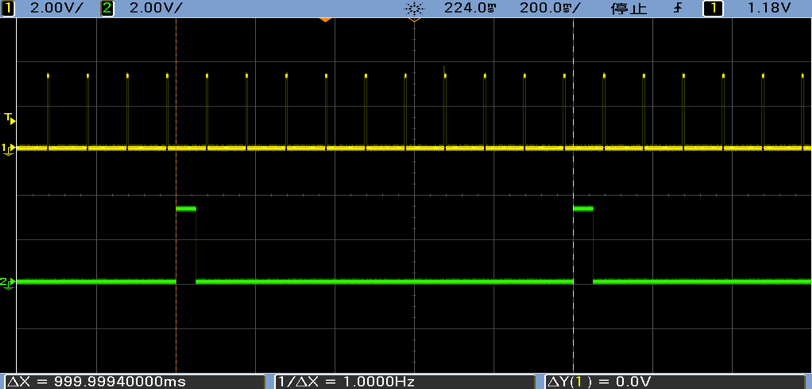
PPS jitter measurement
Connect MiiVii device's PPS pin and SYNC_IN pin. Run sample code (pps_test) for real-time analytics on the received timestamp.
|
|---|
| Figure Sync Pin Connection Schematic |

|
|---|
| Figure PPS Test Result |

Interface characteristics
Does not support hot plug.
Supports signal transmission with a coaxial cable of up to 15 meters.
It is recommended to support cameras with output resolutions of 720p, 1080p, 4k and other resolutions.
Camera support
No | Brand | Camera Name | Support Type | Shutter Type | Resolution | Frame Rate |
|---|---|---|---|---|---|---|
| 1 | Entron | S001A | formal | rolling | 1280*720 | 30fps |
| 2 | Sensing | SG1-AR0143-0101-GMSL-Hxxx | formal | rolling | 1280*720 | 30fps |
| 3 | Sensing | SG1-AR0147-0101-GMSL-Hxxx | formal | rolling | 1280*720 | 30fps |
| 4 | Sensing | SG2-AR0231-0202-GMSL-Hxxx | formal | rolling | 1920*1080 | 24fps |
| 5 | Sensing | SG2-AR0233-GW5200-GMSL2-Hxxx | formal | rolling | 1920*1080 | 30-60fps |
| 6 | Entron | F001* | Beta | rolling | 1280*720 | 25fps |
Connection
Please refer to 'Interfaces'
Camera Setup
Regarding setup your GMSL camera.
If you are using Jetpack 4.4 and before, please refer to MiiVii Setting.
If you are using Jetpack 4.5 and after, please refer to miivii settings usage.
Video Output
1. For ease of use, the device provides three executable files cameras_egl_demo, cameras_opencv_demo, cameras_sdk_demo to display GMSL camera images. For details, please refer to /opt/miivii/features/gmsl_camera
cameras_opencv_demo: Use v4l and opencv directly to obtain camera images. (recommend)
cameras_sdk_demo: SDK compatible with GMSL1, uses ASIC to convert the image format, with high operating efficiency. And you can get the time stamp of triggering the shutter through the SDK. (If a timestamp is required, it is recommended, otherwise it is not recommended)
cameras_egl_demo: Use egl as the display part to achieve high efficiency in the display part.
2. Video output is divided into two application scenarios: self-trigger mode and synchronous mode:
(1). Self-trigger mode: the camera triggers according to the internal clock. At this time, the time stamp of the camera cannot be obtained, and the pictures between the cameras cannot be synchronized.
In the case of using the self-trigger mode, there is no need to use any SDK. You can refer to: OpenCV Python Demo,OpenCV C++ Demo
But be aware that you need to perform format conversion yourself. Such as converting from YUYV to BGR format, etc.
(2). Synchronous mode: means that all cameras are triggered by the same trigger signal, and the shutter time is almost strictly synchronized.
In synchronous mode, use OpenCV demo to display the camera screen of /dev/video0. Please note that 1280x720 needs to match the real resolution of the camera. For a 1080p camera, it is 1920x1080.
./bin/cameras_opencv_demo -s 1280x720 -d /dev/video0
In the synchronous mode, use the SDK demo to display the camera screen of /dev/video0. Please note that 1280x720 needs to match the real resolution of the camera. For a 1080p camera, it is 1920x1080.
./bin/cameras_sdk_demo -s 1280x720 -d /dev/video0
Command example:
The first step: compile
cp -ravf /opt/miivii/features ~/
cd ~/features/gmsl_camera
make;
Run OpenCV Demo (Please note that the resolution and the real resolution of the camera must be consistent)
./bin/cameras_opencv_demo -s 1280x720 -d /dev/video0
Run SDK Demo (please note that the resolution and the real resolution of the camera must be the same)
./bin/cameras_sdk_demo -s 1280x720 -d /dev/video0
Run SDK Demo (please note that the resolution and the real resolution of the camera must be the same)
./bin/cameras_egl_demo -s 1280x720 -d /dev/video0
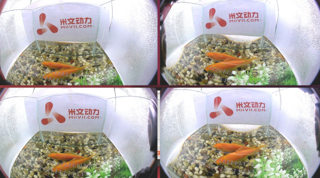
|
|---|
| Figure GMSL Output |
MiiVii offers several demo code:
Algorithm: MiiVii device offers human, vehicle, bicycle detection. Please refer to /opt/miivii/features/algorithm
Acceleration SDK: MiiVii device provides acceleration SDK based on Yolo v3. Please refer to /opt/miivii/features/miivii-accelerator
ROS demo: MiiVii device offers ROS DEMO. Please refer to /opt/miivii/ros_demo
Among them, miivii_msgs is the message rule of ROS. miivii_gmsl is the ROS node of GMSL camer. miivii_detector is the ROS node of object detection.
Besides, MiiVii also open source part of our code in Github. Please visit https://github.com/MiiViiDynamics for more information.
Exception Handling
If bug occurs to you while developing, please check DEBUG log first:
Step 1: Find the position of DEBUG port in 'Interfaces'
Step 2: Connect DEBUG port with a PC using a UART-USB cable1
Step 3: Download Serial debugging tool in the PC, set Baud to 115200
Step 4: Check DEBUG log
[1]:According to the information in 'Interfaces', select the RS232-USB cable or TTL-USB cable。
1.Function Introduction
Miivii burning tool, suitable for Miivii series products.The tool has two main functions: burn images and clone images. You can burn the official image of Miivii power for Miivii devices using an X86 architecture PC as the burn host. After developing a Miivii device for some time, you can save your progress by cloning an existing device images and burning it to other Miiivii devices.
2.Prepare Software And Hardware
2.1. Burn The Host Ready
It is necessary to connect the writing host to the Miivii device to burn the images. The recommended figuration of the write host is as follows:
● CPU uses Intel core series processors with X86 architecture
● Memory 8GB DDR3 and above
● Spare hard disk capacity 40G and above
● The system is Ubuntu Linux X64 v16.04 or V18.04
2.2. Prepare Miivii Burn Tools And Miivii Device Images
● Low for a link: https://en.miivii.com/index.php?s=index/category/index&id=119
● Download the Miivii burn tool
● Download the Miivii device image and the image MD5 value
● Store the above files in the same path as the burn host
● Supports simultaneous burning of multiple identical devices, but does not support simultaneous burning of multiple different devices
Note: The file storage path cannot contain Chinese characters or special characters
2.3. Prepare The Hardware
● Miivii equipment and power, USB data cable
3. The Operation
3.1 Hardware Connection
● Connect the writing port of Miivii device to the writing host through USB data cable
3.2 Use of Software
3.2.1. Images Burn
● Copy the images and MD5 values to the imGS folder of the burn tool
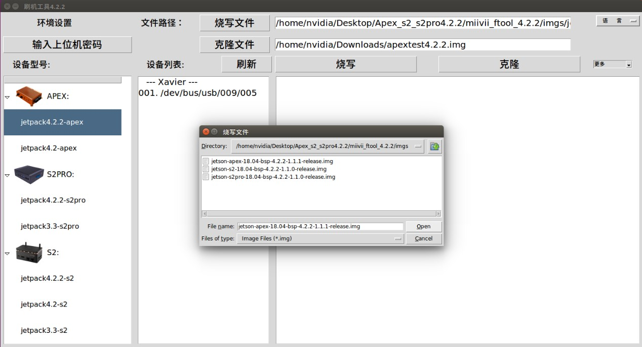
● Go to the bin folder of the burn tool and open the Burn tool "MVflasher"

● Click [Enter upper computer password] button, enter the current burning host boot password
● In the device model on the right, select the device you want to burn and the Images version. Click the "Burn file" button to select the specific image for burn
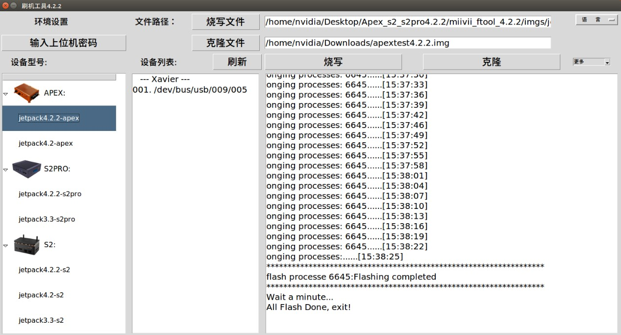
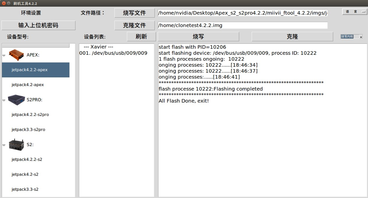
● Click the "burn" button to enter the burn process:
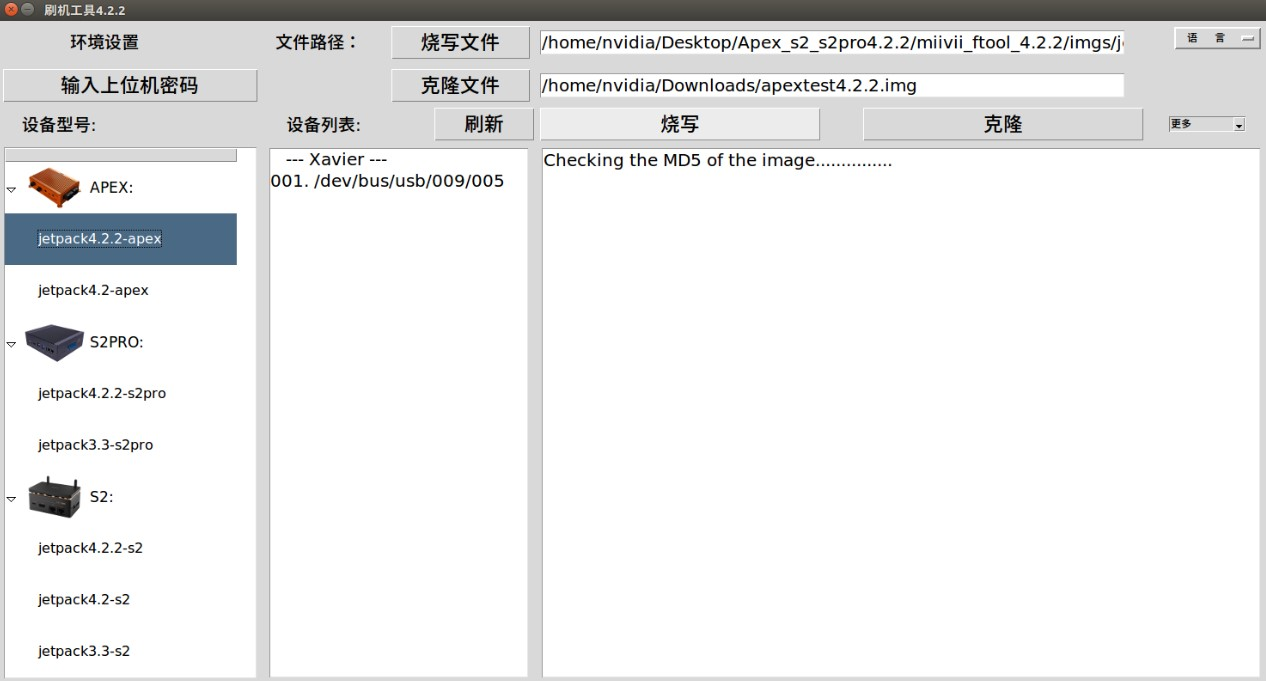
● Images burning usually takes more than 15 minutes to complete. Please be patient:
3.2.2. Images Clone
● Enter the FORCE_Recovery mode of the Miivii device to be cloned according to method 3.1, and open the burn tool
● Click [Enter upper computer password] button,enter the current burning host boot password
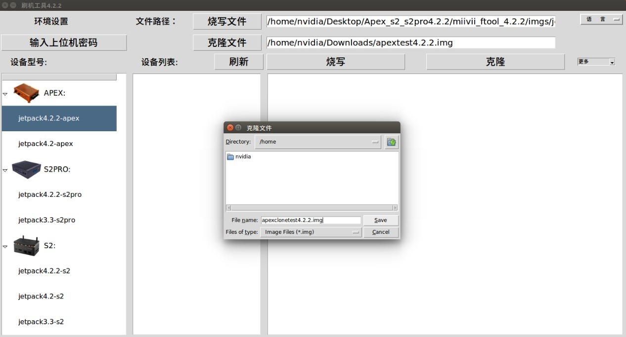
● Click the "Clone file" button to modify the path and name of the clone file saved in the write host :
Note: The file storage path cannot contain Chinese characters or special characters
● Click the "clone" button to enter the cloning process, as shown in the figure:
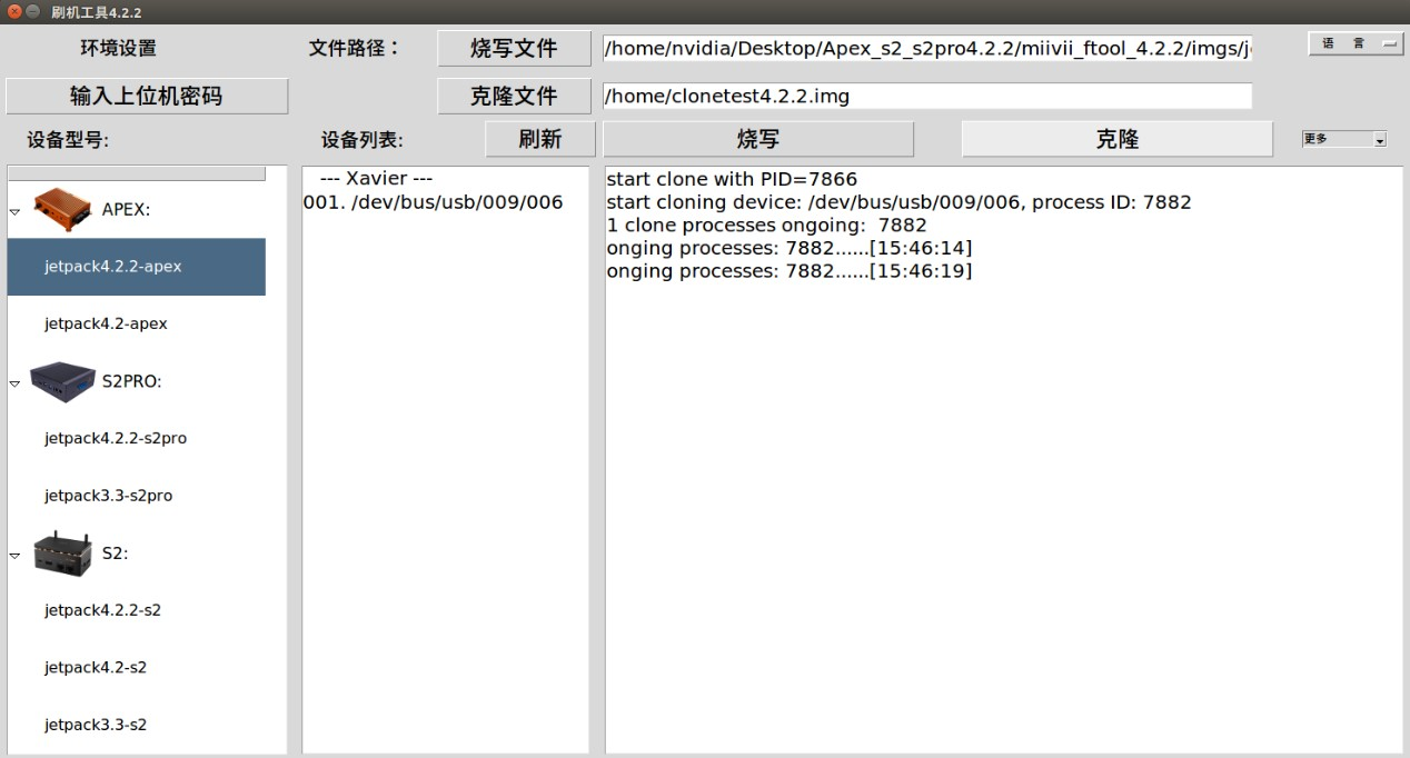
● Images cloning usually takes more than 30 minutes to complete:
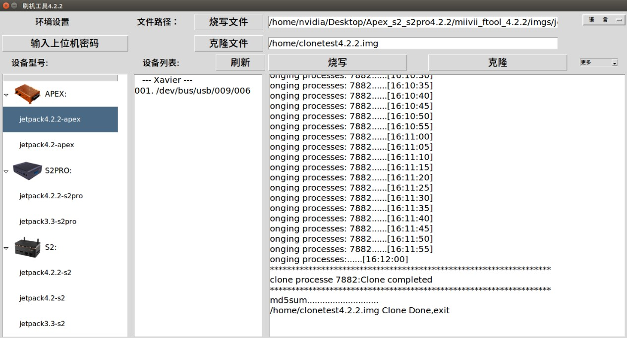
● Cloning completed, will generate a clone image and MD5 file, please burn again according to step 3.2.1 operation
Note: if you encounter problems in the cloning process, please contact Miivii power for help:
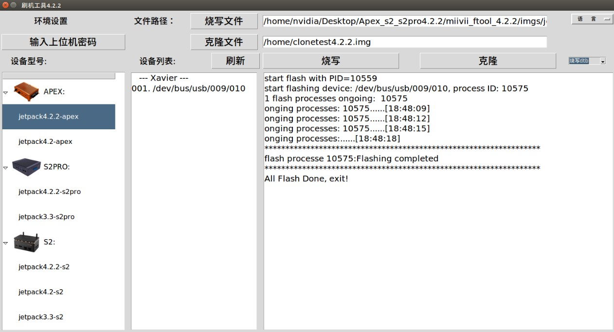
Attached 1. Kernel and DTB burn
Miivii device burn tool can burn system kernel and DTB separately, click [more] in the upper right corner to choose.

Note: before you do this in meters, power after confirmation: helpdesk@miivii.com
Attached 2. Self-test For Burning Problems
If you encounter burning problem, please first conduct self-test according to the following items:
● Check whether the upper computer boot password is entered in the upper left corner of the burn tool
● Check whether to enter the Recovery mode, can be identified by the lsusb command
● Check whether Micro USB cable quality is up to standard and whether it is only a dual-core cable used for charging
● Check upper computer, whether it is x86-64 architecture desktop, notebook.(Server, embedded device, virtual machine and other devices are not supported temporarily)
● Check whether the upper computer system is Linux 1604 /1804
● Check the disk format, the recommended disk format for burning hosts is EXT4
● Check whether the upper computer capacity is enough
● The Images and burn tool storage path cannot have Chinese or other special characters