Please read manual carefully before install, operate, or transport MiiVii device.
Ensure that the correct power range is being used before powering the device.
Avoid hot plugging.
To properly turn off the power, please shut down the Ubuntu system first, and then cut off the power. Due to the particularity of the Ubuntu system, on the Nvidia developer kit, if the power is turned off when the startup is not completed, there will be a 0.03% probability of abnormality, which will cause the device to fail to start. Due to the use of the Ubuntu system, the same problem also exists on the Miivii device.
Do not use cables or connectors other than described in this manual.
Do not use MiiVii device near strong magnetic fields.
Backup your data before transportation or MiiVii device is idle.
Recommend to transport MiiVii device in its original packaging.
Service and support
Technical support
If you encounter problems or you think your product is defective, please email: helpdesk@miivii.com , we will help you solve the problem. You can also visit the MiiVii Technology Forum http://forum.miivii.com , search our knowledge base for solutions to common problems.
Warranty
Warranty period: the warranty period of MiiVii equipment is one year from the date of purchase. Warranty regulations: during the warranty period, if there is any non-human damage to the product, MiiVii will provide free warranty. Please contact helpdesk@miivii.com Get warranty assistance.
Product list
Apex Xavier II+×1
ACDC power adatper×1
PORT 1 I/O cable connector×1
PORT 2 I/O cable connector×1
4 in 1 MINI FAKRA to FAKRA cable connector×2
4G Module×1(optional)
4G Antenna×2
WiFi Module×1(optional)
WiFi Antenna×2
SSD×1(optional)
POE Module×1(optional)
Warranty card×1
QC PASS×1
Table of contents
- Notice
- Service and support
- Table of contents
- About Apex Xavier II+
- chapter 1:Interface description and expansion installation
- Chapter 2: gmsl related configuration and usage
- Chapter 3: Introduction to synchronization interface and related functions
- Chapter 4: UART port and function introduction
- Chapter 5: CAN port and function introduction
- Chapter 6: GPIO port and function introduction
- Chapter 7: extended equipment configuration method
- Appendix 1
- Appendix 2
- Jetpack 4.5 and Above Image Burning
- Instructions for using online system upgrade (OTA)
- Appendix 3
- Appendix 4
- Appendix 5
About Apex Xavier II+
Brief
MiiVii Apex Xavier II+ is an embedded artificial intelligence computer, which can give artificial intelligence computing power to many terminal devices, so as to effectively reduce the landing threshold of artificial intelligence products. Apex Xavier II+ can meet industrial standards such as anti vibration and waterproof, also be able to provide up to 32tops computing power, which can well meet the AI computing needs of low-speed unmanned driving and other scenes. In addition, Apex Xavier II+ can also provide efficient multi-sensor clock synchronization.

Feature
IP65 Protection1
Efficient active fan cooling
8×GMSL2 camera link
-25℃-70℃ Operating temperature
MINI-PCIE and M.2 M 2280 expansions
1:The devices I/O ports are provided with dust-proof and water drainage treatment.
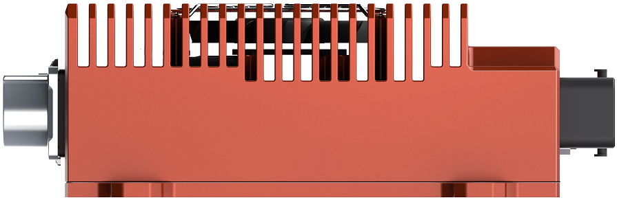
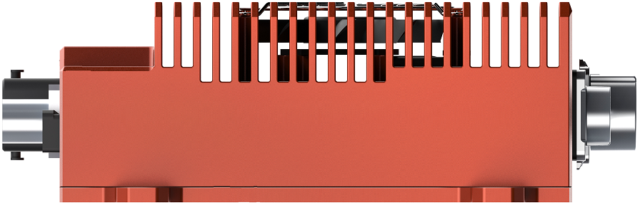
正视图 Front view | 左视图 Left view |
|---|---|
|
|
| 右视图 Right view | 后视图 rear view |
|
|
Specifications
Processor
Specification | |
|---|---|
Processor | NVIDIA Jetson AGX Xavier 32GB |
| AI Performance | Up to 32TOPS |
| CPU | 8-core ARM v8.2 64-bit CPU |
| GPU | 512-core Volta GPU |
| Memory | 32GB 256-Bit LPDDR4 |
| DL Accelerator | 2×NV DLA Engines |
| Storage | 32GB eMMC 5.1 |
| Video Encode | 4x 4Kp60 4x 4Kp60 |
| Video Decode | 2x 8Kp30 4x 4Kp60 |
I/O
Interface | /Specifications |
|---|---|
| Network | 4× Gigabit Port(Optional IEEE 802.3 at PoE+ 25.5W) |
| Camera | 2× GMSL2 4 IN 1 MINI FAKRA TYPE(10V,Transmission distance up to 15 meters,GMSL2 compatible with GMSL1) |
| Video output | 1× HDMI 2.0(TYPE A) |
| USB | 2× USB 3.0(TYPE A) |
| GPIO | 4× In(0-12V) 4× Out(3.3V) |
| CAN FD | 5× CAN FD(With CAN chip Terminal resistor 120Ω) |
| UART | 1× Debug(RS232),3× RS232,2× RS485/RS422 |
| Sync I/O | 1× SYNC_IN(0-12V),1× SYNC_OUT(3.3V), 1× SYNC_PPS(3.3V) |
| Expansion | 1× M.2 M Key(PCIe x4, 2280),1× Mini PCle(For 4G or WiFi expansion),1× Nano SIM Socket |
| Function Key | 1× Power KEY, 1× Reset KEY, 1× Recovery KEY(Button) |
Power Supply
Power Supply | Spec |
|---|---|
| Input Type | DC |
| Input Voltage | Wide input 9-36V DC |
| Typical consumption | 30W |
Mechanical
Mechanical | Spec |
|---|---|
| Dimensions (W×D×H) | 276mm×214mm×68mm (I/O ports and mounting holes included) 240mm×173mm×68mm (I/O ports and mounting holes excluded) |
| Weight | 3.5Kg |
Environmental
Environmental | Spec |
|---|---|
| Operating Temperature | -25℃-70℃ |
| Storage Temperature | -40℃-80℃ |
| Storage Humidity | 10%-90% non-condensing |
| Vibration | 2Grms,10Hz~500Hz,1h/axis |
| Protection | IP5X(standard) IP65(Optional ) |
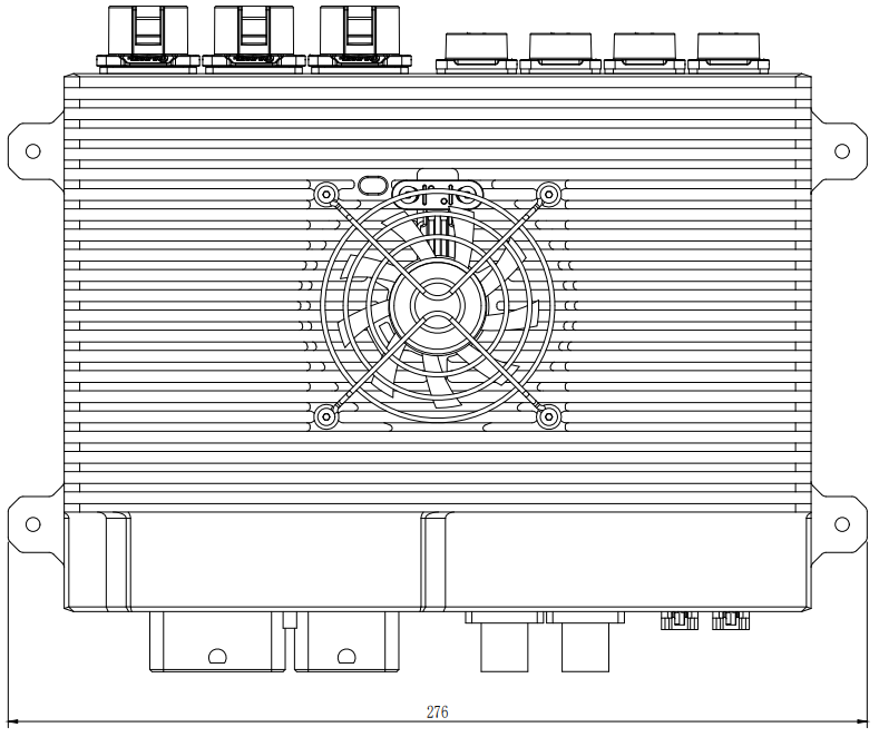
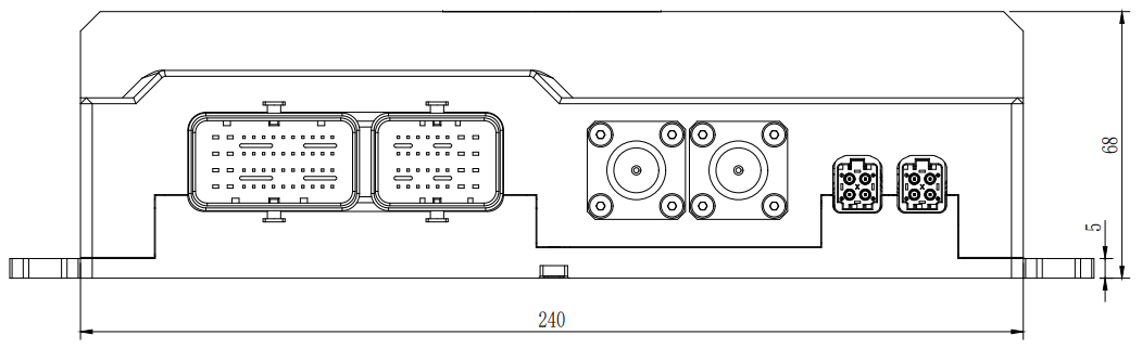
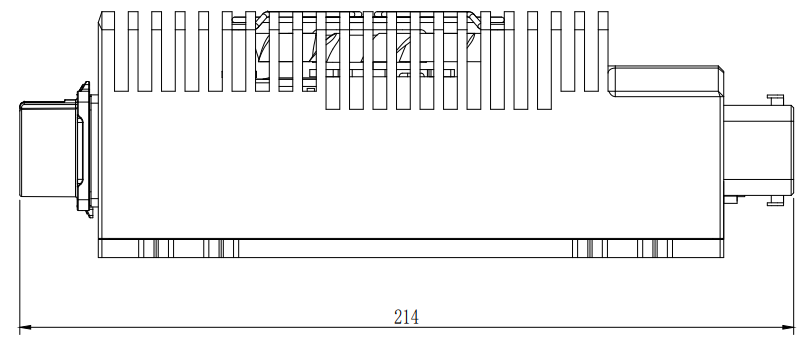
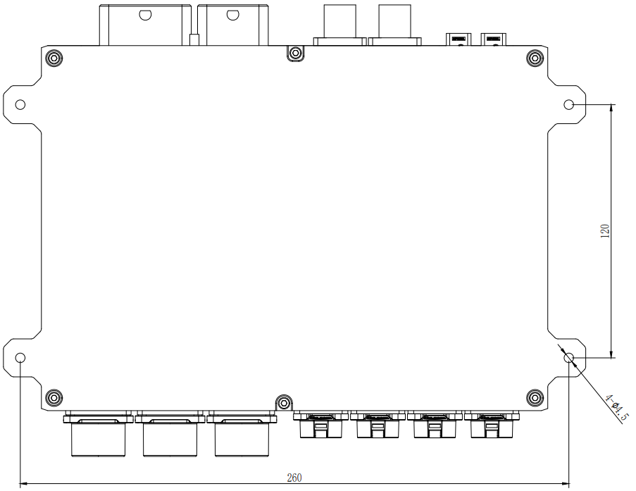
Install Dimension
Apex Xavier II+ size and installation shown in the figure:
Up view(Unit:mm) |
|---|
|
| Front view(Unit:mm) |
|
| Left view(Unit:mm) |
|
| Mounting Hole(Unit:mm) |
|
chapter 1:Interface description and expansion installation
Interface description
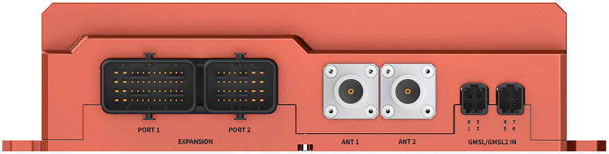
Front Panel
|
|---|
| Figure Apex Xavier II+ Front Panel |

Interfaces | Interface name | Description |
|---|---|---|
| EXPANSION PORT① | IO_1 | 1× RS232 DEBUG 3× RS232 2× RS422/RS485 2× CAN FD(with CAN chip and 120Ω Terminal resistance) 1× SYNC_PPS (3.3V) 1× SYNC_OUT(3.3V) 1× SYNC_IN (Logic High 1V-12V, Logic Low 0V-0.8V) 1× POWER_ONKEY 1× FORCE_RECOVERY 1× RESET key |
| EXPANSION PORT② | IO_2 | 1× DC in 9-36V 3× CAN FD(with CAN chip and 120Ω Terminal resistance) 8× GPIO(4×In(Logic High 1V-12V, Logic Low 0V-0.8V),4×Out(3.3V)) 1× FAN power port(5v PWM) |
| ANT1 | ANT1 | 4GAntenna extension port or 2.4G/5.8G WIFI Antenna extension port |
| ANT2 | ANT2 | 4GAntenna extension port or 2.4G/5.8G WIFI Antenna extension port |
| GMSL/GMSL2 4 IN 1 MINI FAKRA | GMSL /GMSL2 in | 8× GMSL/GMSL2 camera port |
Multi-functional interface is introduced as follows:
Expansion port ① and expansion port ② are located in the front of apex Xavier II +, as shown in the figure:
|
|---|
| Figure Multi function interface diagram |

The camera interface pin is defined as follows:
|
|---|
Figure interface diagram of apex Xavier II + camera |

Circuit | Device node |
|---|---|
| 0 | video0 |
| 1 | video1 |
| 2 | video2 |
| 3 | video3 |
| 4 | video4 |
| 5 | video5 |
| 6 | video6 |
| 7 | video7 |
Expansion port ① interface signal definition
|
|---|
| EXPANSION PORT ① |

Interface name | Pin NO. | Signal definition | Description |
| UART(DEBUG) 4 | G1 | UART(DEBUG)_RX | UART(DEBUG):232-RX |
| H1 | UART(DEBUG)_TX | UART(DEBUG):232-TX | |
| J1 | GND | Ground | |
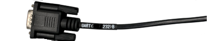
| UART(232)B | D1 | UART(232)B_RX | UART(232)B:232-RX |
| E1 | UART(232)B_TX | UART(232)B:232-TX | |
| F1 | GND | Ground | |
| UART(232)C | B2 | UART(232)C_RX | UART(232)C:232-RX |
| A2 | UART(232)C_TX | UART(232)C:232-TX | |
| A3 | GND | Ground | |
| UART(422/485)A | K1 | UART(422T+/485_A)A | UART(422/485)A:422A/485_A |
| L1 | UART(422T-/485_B)A | UART(422/485)A:422B/485_B | |
| M1 | UART(422R+) | UART(422)A:422_C | |
| M2 | UART(422R-) | UART(422)A:422_D | |
| L2 | GND | Ground | |
| UART(422/485)B | G2 | UART(422T+/485_A)B | UART(422/485)B: 422A/485_A |
| F2 | UART(422T-/485_B)B | UART(422/485)B: 422B/485_B | |
| E2 | UART(422R+) | UART(422)B:422_C | |
| D2 | UART(422R-) | UART(422)B:422_D | |
| C2 | GND | Ground | |
| CAN_A | B3 | CAN_A_L | CAN_A Low |
| C3 | CAN_A_H | CAN_A High | |
| CAN_B | D3 | CAN_B_L | CAN_B Low |
| E3 | CAN_B_H | CAN_B High | |
| PPS_A | A1 | PPS_A_RX | PPS_A:TTL-RX |
| B1 | PPS_A_TX | PPS_A:TTL-TX | |
| C1 | GND | Ground | |
| F3 | PPS_A_SYNC | PPS_A_SYNC | |
| G3 | GND | Ground | |
| UART(232)A | K2 | UART(232)A_RX | UART(232)A:232-RX |
| J2 | UART(232)A_TX | UART(232)A:232-TX | |
| H2 | GND | Ground | |
| H3 | null | null | |
| J3 | GND | Ground | |
| SYNC_IO | K3 | SYNC_IN | Sync in同步信号 |
| L3 | GND | Ground | |
| M3 | SYNC_OUT | Sync out同步信号 | |
| M4 | GND | Ground | |
| K4 | GND | Ground | |
| RESET key | J4 | RESET | |
| RECOVERY key | G4 | FORCE_RECOVERY | |
| POWER key | E4 | POWER_ONKEY | |
| GND | H4 | GND | Ground |
| F4 | |||
| D4 |
4 UART (debug) interface is the debug interface*
Expansion port ② interface signal definition
|
|---|
| EXPANSION PORT② |

| Interface name | Pin NO. | Signal definition | Description |
| POWER | H1 | VIN | DC +(DC) |
| H2 | VIN | DC +(M20,Brown) | |
| H3 | VIN | DC +(M20,Grey) | |
| H4 | VIN | DC + | |
| G1 | GND | DC -(DC) | |
| G2 | GND | DC -(M20,Blue) | |
| G3 | GND | DC -(M20,Black) | |
| G4 | GND | DC - | |
| CAN_C | D3 | CAN_C_L | CAN_C Low |
| C3 | CAN_C_H | CAN_C High | |
| CAN_D | B3 | CAN_D_L | CAN_D Low |
| A3 | CAN_D_H | CAN_D High | |
| CAN_E | B1 | CAN_E_L | CAN_E Low |
| A1 | CAN_E_H | CAN_E High | |
| 8路 GPIO口 | A2 | GPIO_1 | GPIO_IN |
| C2 | GPIO_13 | ||
| E3 | GPIO_12 | ||
| F3 | GPIO_11 | ||
| E2 | GPIO_24 | GPIO_OUT | |
| F1 | GPIO_26 | ||
| D1 | GPIO_33 | ||
| F4 | GPIO_7 | ||
| GND | B2 | GND | Ground |
| D2 | |||
| F2 | |||
| E1 | |||
| E4 | |||
| C1 | |||
| FAN | B4 | GND | Ground |
| A4 | DC_5V | DC + | |
| D4 | FAN_TACH | Speed | |
| C4 | FAN_PWM | regulate |
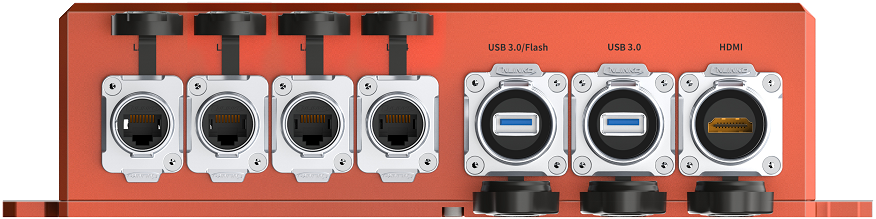
Rear interface
|
|---|
Figure schematic diagram of apex Xavier II + rear interface |

Interface | Interface name | Description |
|---|---|---|
| RJ45 network port | LAN1 | Independent gigabit network port, compatible with 100Mbps network port Optional IEEE 802.3at Poe 25.5w |
| RJ45 network port | LAN2 | |
| RJ45 network port | LAN3 | |
| RJ45 network port | LAN4 | |
| USB 3.0/Flash | USB 3.0/Flash | USB 3.0(TYPE A)/Recovery Flashing port |
| USB3.0 | USB 3.0 | USB 3.0(TYPE A) |
| HDMI | HDMI | HDMI 2.0(TYPE A) |
Description of IO adapter cable
Apex Xavier II + is attached with two IO transfer cables, corresponding to expansion port ① / port ②
Port 1 adapter cable description
The extension port ① adapter cable has 10 DB9 terminals and 3 keys. The functions are shown in the table:
NO. | function | number | Export mode |
|---|---|---|---|
| 1 | UART_232 | 4 | black DB9 terminals |
| 2 | UART_485 | 2 | red DB9 terminals |
| 3 | CAN(CAN FD) | 2 | white DB9 terminals |
| 4 | PPS | 1 | blue DB9 terminal |
| 5 | Synchronization signal | 1 | green DB9 terminal |
| 6 | 3 keys | 3 | 1×RESET key, 1×RECOVERY key, 1×POWER_ON KEY |
|
|---|
Figure physical drawing of IO adapter line |

Function keys
Apex Xavier II + extension port ① provides three function keys – Reset key and Power_ On key and Force_ Recovery key.
|
|---|
Figure physical drawing of function keys |

Key name | Key function | Color |
|---|---|---|
| RESET key | Device restart | White |
| POWER_ONKEY | Device start | Red |
| FORCE_RECOVERY | Enter recovery mode | Black |
Port 2 Adapter description
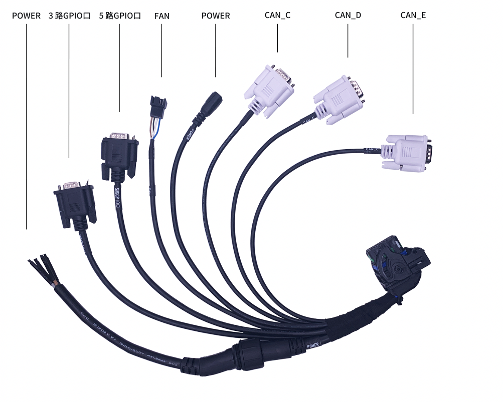
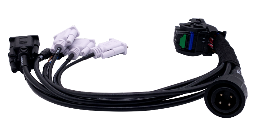
Expansion port ② adapter cable has 2 power terminals, 5 DB9 terminals and 1 external expansion fan interface. The functions are shown in the table:
NO. | function | number | Export mode |
|---|---|---|---|
| 1 | DC in | 1 | 1× 5x2.5 DC port 1× 4pin M20 connector |
| 2 | CAN(CAN FD) | 3 | 3× DB9 terminals |
| 3 | GPIO | 8 | 2× DB9 terminals |
| 4 | FAN | 1 | 1× 4core 5V PWM terminal |
|
|---|
Figure physical drawing of IO adapter line |
Power interface
Apex Xavier II + adapter provides 2-way power input interfaces, which are electrically connected in parallel.
Figure physical drawing of DC power interface |

|
|---|
Figure physical drawing of M20 plug-in power interface |
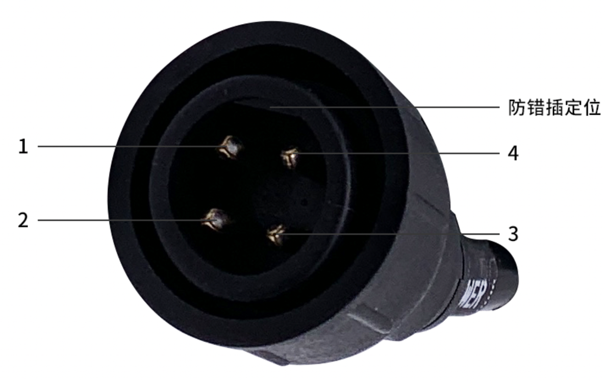
Pin | Signal definition | Description |
|---|---|---|
| 1 | VIN | DC+ |
| 3 | VIN | DC+ |
| 2 | GND | DC- |
| 4 | GND | DC- |
M20 plug-in power adapter
|
|---|
Figure physical drawing of M20 plug-in power adapter |
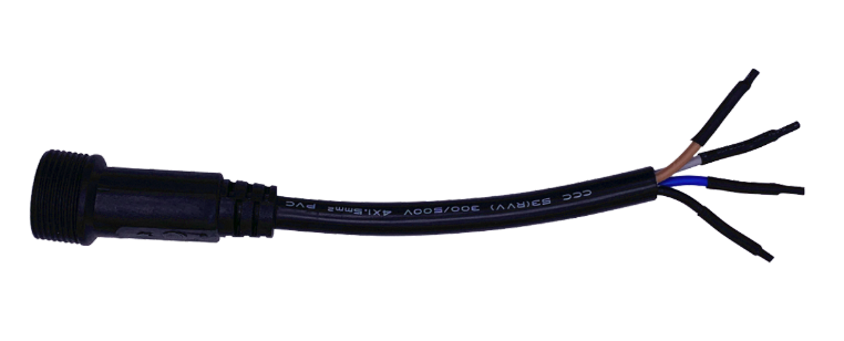
The line sequence of aviation plug-in power transfer line in apex Xavier II + transfer line is described as follows. For comparison with the interface signal of expansion port ②, see the interface description.
Color | Signal definition | Description |
|---|---|---|
| Brown | VIN | DC+ |
| Grey | VIN | DC+ |
| Blue | GND | DC- |
| Black | GND | DC- |
Fan connecting line and pin definition
Apex Xavier II + supports an external 5v-PWM fan output.
As shown in the figure:
|
|---|
Figure physical drawing of fan link line |
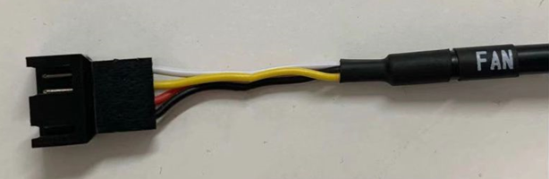
Color | 信号定义 | 接口说明 |
|---|---|---|
| Black | GND | Ground |
| Red | DC_5VFAN | DC+ |
| Yellow | FAN_TACH | Fan speed |
| Blue | FAN_PWM | Speed adjust |
Chapter 2: gmsl related configuration and usage
Connection mode
Apex Xavier II + provides 8-way gmsl2 camera interface. The interface characteristics are described as follows:
|
|---|
Figure interface diagram of apex Xavier II + camera |
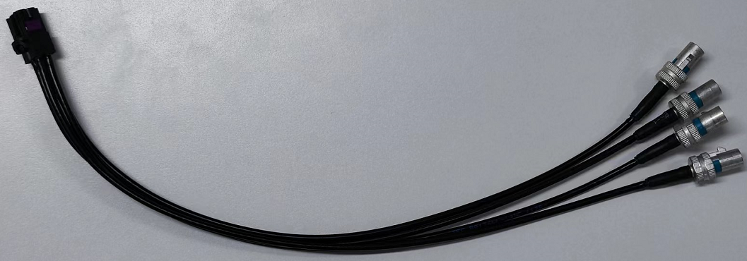
Insert the black terminal of the four in one gmsl harness equipped in the equipment package into the equipment end, and the other side is the male of four standard fakra terminals, which can be connected to four gmsl cameras
|
|---|
Figure schematic diagram of apex Xavier II + four in one gmsl harness |
Interface characteristics
- Hot plug is not supported.
- Support signal transmission of up to 15m coaxial cable.
- It is recommended to support cameras with output resolutions of 720p, 1080p, 4K and other resolutions.
- Apex Xavier II + supports two groups of 8-way gmsl2 camera input.
- The power supply voltage of apex Xavier II + for gmsl2 camera is 10V. Please confirm the allowable voltage range of the camera used to avoid over-voltage burning the camera.
- The 8-channel gmsl2 camera can be triggered by the synchronization signal of the same fixed output frequency.
- For the product gmsl camera support list, please visit Appendix 4
Camera Setup
Regarding setup your GMSL camera.
If you are using Jetpack 4.5 and after, please refer to MIIVII Settings usage
Fast verification
Use Cheese in Linux to quickly verify the video.
Refer to the following video:
1. 2. 3. 4. | Confirm that the gmsl camera has been set right Open Cheese Confirm that the resolution has been set right Choose the corresponding device name.(“video4” in this video) |
Please notice that since cheese can not set the image format, the output format of the camera may not match the default format of cheese, so there might be color difference. This is a problem of cheese.
Video Output
1.For ease of use, the device provides three executable files cameras_egl_demo, cameras_opencv_demo, cameras_sdk_demo to display GMSL camera images. For details, please refer to /opt/miivii/features/gmsl_camera
cameras_opencv_demo: Use v4l and opencv directly to obtain camera images. (recommend)
cameras_sdk_demo: SDK compatible with GMSL1, uses ASIC to convert the image format, with high operating efficiency. And you can get the time stamp of triggering the shutter through the SDK. (If a timestamp is required, it is recommended, otherwise it is not recommended)
cameras_egl_demo: Use egl as the display part to achieve high efficiency in the display part.
2.The device supports the use of GStreamer to output video streams. The methods of image acquisition and display are as follows:
720P:
gst-launch-1.0 -v v4l2src device="/dev/video1" ! video/x-raw,framerate=30/1,width=1280,height=720,format=UYVY ! xvimagesink
1080P:
gst-launch-1.0 -v v4l2src device="/dev/video0" ! video/x-raw,framerate=60/1,width=1920,height=1080,format=UYVY ! xvimagesink
Please note that since the format of the camera output does not necessarily match the default format of GStreamer, there may be color differences.
3.Video output is divided into two application scenarios: self-trigger mode and synchronous mode::
(1). Self-trigger mode: the camera triggers according to the internal clock. At this time, the time stamp of the camera cannot be obtained, and the pictures between the cameras cannot be synchronized.
In the case of using the self-trigger mode, there is no need to use any SDK. You can refer to: OpenCV Python Demo,OpenCV C++ Demo
But be aware that you need to perform format conversion yourself. Such as converting from YUYV to BGR format, etc.
(2). Synchronous mode: means that all cameras are triggered by the same trigger signal, and the shutter time is almost strictly synchronized.
In synchronous mode, use OpenCV demo to display the camera screen of /dev/video0. Please note that 1280x720 needs to match the real resolution of the camera. For a 1080p camera, it is 1920x1080.
./bin/cameras_opencv_demo -s 1280x720 -d /dev/video0
In the synchronous mode, use the SDK demo to display the camera screen of /dev/video0. Please note that 1280x720 needs to match the real resolution of the camera. For a 1080p camera, it is 1920x1080.
./bin/cameras_sdk_demo -s 1280x720 -d /dev/video0
commands:
first:compile
cp -r /opt/miivii/features ~/
cd ~/features/gmsl_camera
sudo make;
Run OpenCV Demo(please note that the resolution must be consistent with the real reaolution of the camera)
./bin/cameras_opencv_demo -s 1280x720 -d /dev/video0
Run SDK Demo(please note that the resolution must be consistent with the real reaolution of the camera)
./bin/cameras_sdk_demo -s 1280x720 -d /dev/video0
Run EGL Demo(please note that the resolution must be consistent with the real reaolution of the camera)
./bin/cameras_egl_demo -s 1280x720 -d /dev/video0
|
|---|
Figure GMSL output |

To turn on multiple cameras in one process and get the timestamp:
Test method for GMSL/GMSL2 timestamp
How to get the detailed log and log descriptiom?
command | result |
|---|---|
# export CHECK_TIME=1 sudo jetson_clocks rm /tmp/cameras_sdk_demo.log ./bin/cameras_sdk_demo -s 1280x720 -d /dev/video0 | Log will be shown on the screen Under the path /tmp/,cameras_sdk_demo.log will be generated |
Description of the log file
| field | unit | meaning | test method |
|---|---|---|---|
| Timestamp | ns | The time when the frame was triggered | The trigger time obtained from the queue according to the transmission delay |
| FrameInterval | ns | Frame Interval time interval between two trigger times | difference between last Timestamp |
| FrameTransferDelay | ns | Frame Transfer Delay | LinuxGetFrameTime - Timestamp |
| LinuxGetFrameTime | ns | Linux system time when getting the frame | Linux system time when receiving the frame |
| LinuxFrameInterval | ns | time interval between 2 image receiving time | difference between last LinuxGetFrameTime |
How to confirm whether the timestamp is correct?
In the code, the validity of the timestamp is determined by checking FrameInterval
execute:
# export CHECK_TIME=1
sudo jetson_clocks
rm /tmp/cameras_sdk_demo.log
./bin/cameras_sdk_demo -s 1280x720 -d /dev/video0
If the timestamp is normal,the content of /tmp/cameras_sdk_demo.log will be as follow,only one line :
Timestamp : 1620897955083817280 FrameInterval : 1620897955083817280 FrameTransferDelay : 66992720 LinuxGetFrameTime : 1620897955150810000 LinuxFrameInterval : 1620897955150810000
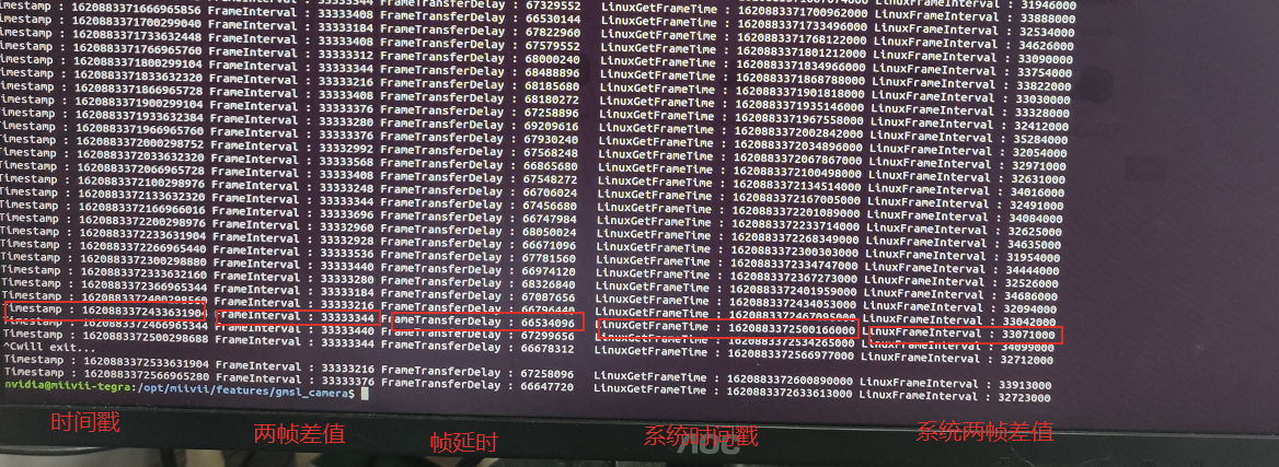
Or if the timestamp is abnormal,there will be multiple records in /tmp/cameras_sdk_demo.log:
Timestamp : 1620958367246484576 FrameInterval  :  1620958367246484576 FrameTransferDelay : 67111424 LinuxGetFrameTime : 1620958367313596000 LinuxFrameInterval : 1620958367313596000
Timestamp : 1620958739646034432 FrameInterval  :  1620958739646034432 FrameTransferDelay : 67403568 LinuxGetFrameTime : 1620958739713438000 LinuxFrameInterval : 1620958739713438000
Timestamp : 1620958748796023808 FrameInterval  :  1620958748796023808 FrameTransferDelay : 80901192 LinuxGetFrameTime : 1620958748876925000 LinuxFrameInterval : 1620958748876925000
Timestamp : 1620958789795973504 FrameInterval  :  1620958789795973504 FrameTransferDelay : 72186496 LinuxGetFrameTime : 1620958789868160000 LinuxFrameInterval : 1620958789868160000
Timestamp : 1620959793244763712 FrameInterval  :  1620959793244763712 FrameTransferDelay : 73185288 LinuxGetFrameTime : 1620959793317949000 LinuxFrameInterval : 1620959793317949000
Timestamp : 1620959854794691840 FrameInterval  :  1620959854794691840 FrameTransferDelay : 68099160 LinuxGetFrameTime : 1620959854862791000 LinuxFrameInterval : 1620959854862791000
Timestamp : 1620960274844196896 FrameInterval  :  1620960274844196896 FrameTransferDelay : 68391104 LinuxGetFrameTime : 1620960274912588000 LinuxFrameInterval : 1620960274912588000
Timestamp : 1620960283994186240 FrameInterval  :  1620960283994186240 FrameTransferDelay : 71857760 LinuxGetFrameTime : 1620960284066044000 LinuxFrameInterval : 1620960284066044000
Timestamp : 1620960291394178080 FrameInterval  :  1620960291394178080 FrameTransferDelay : 68419920 LinuxGetFrameTime : 1620960291462598000 LinuxFrameInterval : 1620960291462598000
How to confirm the accuracy of the timestamp?
| Command | method |
|---|---|
Save the screen log in a file export CHECK_TIME=1 sudo jetson_clocks ./bin/cameras_sdk_demo -s 1280x720 -d /dev/video0 > log |
|
How to confirm the stability of the image transmission delay?
Confirm the image transmission delay
Prior knowledge
GMSL type | resolution | typical camera model | transmission delay |
|---|---|---|---|
| GMSL1 | 720p | SG1-AR0143-0101-GMSL-Hxxx | About 60ms |
| GMSL2 | 1080p | SG2-AR0231-0202-GMSL-Hxxx | About 100ms |
Turn on the camera at a frame rate lower than the transmission delay. Since the transmission delay is less than the frame interval , the cache of the timestamp is 1. Therefore, there will be no other problems introduced by the software. What is measured is the real physical delay
Please notice that do not to use the frame rate corresponding to the transmission delay, the jitter of the transmission delay will cause inaccurate time stamp。
| command | method |
|---|---|
Apex Xavier II Seriesexport CHECK_TIME=1 sudo jetson_clocks ./bin/cameras_sdk_demo -s 1280x720 -d /dev/video0 -r 30-0 -r 30-0 indicates that the frame rate of the set off-camera trigger is 30 | FrameTransferDelay is the actual transfer delay |
Chapter 3: Introduction to synchronization interface and related functions
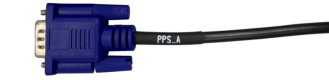
PPS connecting line and pin definition
Apex Xavier II + supports one PPS synchronization signal output with a baud rate of 9600. It corresponds to a dark blue DB9 terminal in the IO adapter line, as shown in the figure:
For the usage of PPS synchronization function, please refer to "PPS synchronization mode" in "synchronization function instructions".
|
|---|
Figure physical drawing of PPS synchronous transfer line |
Pin definition:
Figure PPS synchronization interface pin number diagram |

| PPS | |
| Pin | Signal |
| 1 | GND |
| 2 | PPS_A_RX |
| 3 | PPS_A_TX |
| 5 | GND |
| 6 | PPS_A_SYNC |
Sync connector and pin definition
Apex Xavier II + supports one channel of sync out and one channel of sync in synchronization signal6. Corresponding to a dark green DB9 terminal in the IO adapter line, as shown in the figure:
|
|---|
Figure physical drawing of sync IO adapter line |

SYNC_ Definition of dp9 terminal pin of IO:
Figure sync IO interface pin number diagram |
| Sync | |
| Pin | Signal |
| 1 | SYNC_IN_A |
| 2 | SYNC_OUT_A |
| 3 | NC |
| 6 | GND |
| 7 | GND |
| 8 | GND |
6 For the usage of sync out and sync in synchronization functions, please refer to the "sync out synchronization mode" and "sync in synchronization mode" in the "synchronization function instructions".
External GPS sync
The NMEA output serial port of GPS connects with UART (232) B hardware serial port of apex Xavier II + (the baud rate of serial port is 9600), and the mapping to Linux system is / dev / ttyuart_ 232_ B equipment node.
The PPS second pulse output signal line of GPS is connected to the sync of apex xaiver II +_ Pin1 pin of IO line is mapped to Linux system as / dev / miivii-sync-in-a device node.
In GPS timing mode, the above two nodes will be occupied by the background GPS timing processing program. Do not perform other operations on these two nodes, otherwise the GPS timing function will be interrupted.
Baud rate adjustment of GPS timing serial port
The baud rate of GPS timing serial port node is adjustable:
In / etc / SYSTEMd / sync_ auto. SH script, as follows:
For example: change to 115200
/usr/local/bin/sync_ auto 115200 > /var/log/miivii_ sync. log &
If the baud rate parameter is not filled in, it defaults to 9600
The baud rate parameters supported are as follows:
2400 4800 9600 57600 115200 460800
The device supports three synchronization methods, namely: PPS, Sync in and Sync out synchronization. The synchronization error is 0.1-1 μs.
|
|---|
| Figure, Schematic diagram of equipment synchronization wiring |

How to use the sync function
PPS sync mode
The device outputs PPS signal7 (one pulse is generated per second with a pulse width of 50ms), and sends NMEA GPRMC message of the generation time of the rising edge of the pulse through TX pin of serial port (UART / RS232). Message example:
$GPRMC,060249.000,A,3949.63046,N,11616.48565,E,0.296,,291118,,,A*4d
7 for the hardware connection mode of PPS signal, see "PPS connection line and pin definition" in "Introduction to synchronous interface and related functions"
Where "060249.000" is the time stamp (UTC time) when the pulse is generated per second. The format is "hour minute second. 000", and the normal time is in the whole second format. Sensors supporting PPS synchronization mode will calibrate their own clock system through the received PPS and GPRMC messages to keep it consistent with the system clock of the equipment. The sampling time of the sensor will be sent to the device together with the data as a timestamp. So far, the system obtains the system time of sensor sampling and completes the synchronization.
|
|---|
Figure PPS synchronization schematic diagram |

Synchronization verification (RS-LiDar-16 sensor):
When the sensor connects with Apex Xavier II using only data wire, device ROS Node sends hardware timestamp to the system, which is determined by sensor’s internal clock. As shown below, there is a big difference between hardware timestamp and system time.
|
|---|
Figure RS-LiDAR-16 comparison of the timestamps between the hardware and system(before synchronization) |

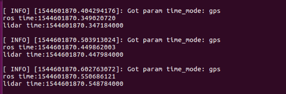
When the sensor is connected to the PPS of the device_ A_ Sync and PPS_ A_ After TX, the ROS node of the sensor uploads data to the operating system. The hardware timestamp in the data is the time of the internal clock of the sensor after PPS timing, which is consistent with the system time of the device. At this time, print the received hardware timestamp in the Ubuntu operating system and compare it with the system time (ROS:: time:: now) when the data is received. When the difference between the two is less than 100ms, it indicates that the PPS function is effective.
|
|---|
Figure comparison between data timestamp and system time |
Sync out Method
The device supports sync out synchronization signal8
8For the hardware connection mode of sync out signal, see "sync connection line and pin definition" in "Introduction to synchronization interface and related functions"
The device can output a 1-30Hz pulse signal with a pulse width of 5ms through the sync out pin to trigger the external sensor to start sampling. At the same time, the equipment will record the generation time of the rising edge of the pulse. After the sensor completes sampling, the equipment will associate the recorded time with the data returned by the sensor as the time stamp of the data. So far, the system obtains the system time of sensor sampling and completes synchronization.
|
|---|
Figure sync out synchronization schematic diagram (25Hz) |

At the same time, the device also provides the sync out synchronization function of gmsl interface. See "Chapter II: gmsl related configuration and use methods" for details
Synchronization function verification method: configure the sensor as the external trigger synchronization mode, and confirm whether the trigger frequency of the sensor is sync through rosbag packet capture The frequency value set in CFG. If the deviation is less than 1Hz, the sync out function is effective.
Data transmission time analysis
Test Description: set the frequency of the sync out signal as 10Hz, and measure the time interval between the rising edge of the sync out signal sent by the device and the video frame received by the device.
|
|---|
Figure IO frame transmission timing diagram |

|
|---|
| Figure frame transmission time test results |

The measurement results show that the average frame transmission time is 65.70ms.
Sync in method
The device supports sync in synchronization signal9.
9For the hardware connection mode of sync in synchronization signal, please refer to "sync connection line and pin definition" in "Introduction to synchronization interface and related functions"
Sensors that support sync in synchronization mode will generate and send a pulse signal when starting sampling. The device passes sync_ The in pin receives the pulse signal and records the generation time of the rising edge of the pulse. After the sensor completes sampling, the equipment will associate the recorded time with the data returned by this sensing as the time stamp of the data. So far, the system obtains the system time of sensor sampling and completes the synchronization.
|
|---|
Figure sync in synchronization schematic diagram (10Hz) |

Verification method of synchronization function: print sync in Ubuntu operating system_ The in pin receives the time stamp of the pulse signal. Compare the time stamp with the system time (ROS:: time:: now) of the received sensor data frame. If the difference between the two is less than 100ms, it indicates that the sync in function is effective.
Synchronization error test method
Measure PPS pulse interval through oscilloscope
Measurement results:
|
|---|
Figure PPS pulse interval |
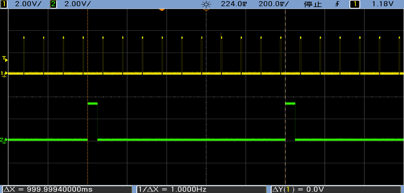
| Theoretical value(μs) | Measured value(μs) | error(μs) | |
|---|---|---|---|
| PPS | 1000000 | 999999.4 | 0.6 |
Measure the sync out pulse interval with an oscilloscope
Measure the interval between two sync out (10Hz) pulses with an oscilloscope and compare it with the theoretical value.
Measurement results:
|
|---|
Figure sync out pulse spacing |
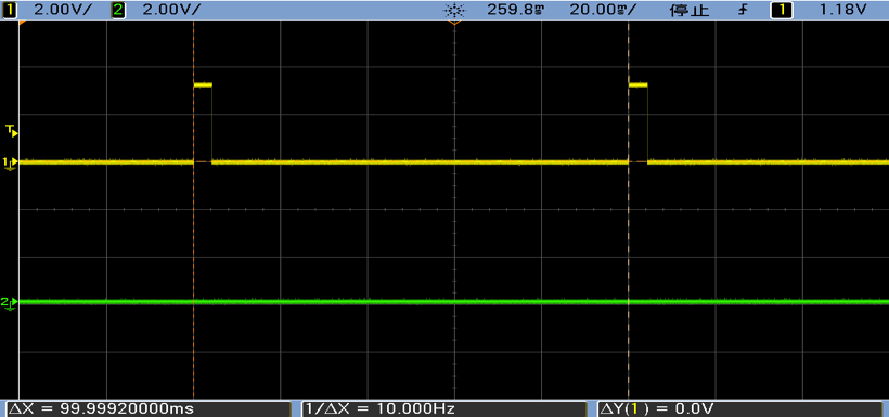
| Theoretical value(μs) | Measured value(μs) | error(μs) | |
|---|---|---|---|
| Sync out | 1000000 | 999999.2 | 0.8 |
Ways to Assess Synchronization Effects on Your Own
Users can measure jitter by timestamp to evaluate the synchronization effect of the device by themselves
Instructions for synchronizing sample code
The sample code provided by MiiVii is used to evaluate the synchronization performance of the device by itself. The usage methods are as follows:
#Enter the following path

cd /opt/miivii/feature/sync_test/bin`

#Test the sync out function

./sync_out_test

#Test the sync in function

./sync_in_test

#test pps function

./pps_test
Sync out jitter measurement
Sample code(sync_out_test) could run real-time analytics on the received timestamp. Time interval, frequency, max deviation and standard deviation are printed out.
|
|---|
Figure sync out example test results |

Sync in jitter measurement
Connect an external signal with fixed frequency to MiiVii device SYNC_IN pin. Run sample code (sync_in_test) for real-time analytics on the received timestamp.Time interval, frequency, max deviation and standard deviation are printed out.
MiiVii device's SYNC_OUT pin could be used as an 25Hz external signal to connect with SYNC_IN pin
|
|---|
Figure sync in example test results |

PPS jitter measurement
Connect MiiVii device's PPS pin and SYNC_IN pin. Run sample code (pps_test) for real-time analytics on the received timestamp.
|
|---|
| Figure IO wiring diagram |

|
|---|
Figure PPS test results |

Chapter 4: UART port and function introduction
UART (232) connecting line and pin definition
Apex Xavier II + supports 4-channel RS232, namely UART (232) a, UART (232) B and UART (232) C. UART (debug) is the debug interface. The black DB9 terminal is used in the transfer line, as shown in the figure:
|
|---|
Figure UART(232) DB9 connector pin assignment |
Pin definition of DB9 terminal of 4 UART (232):
DB9 terminal pin definition of UART (232):
Figure UART(232) pin numbers |
| Interface name | Pin | Signal | Node number |
| UART(DEBUG) | 2 | UART(DEBUG)_RX | DEBUG |
| 3 | UART(DEBUG)_TX | ||
| 5 | GND | ||
| UART(232)A | 2 | UART(232)A_RX | ttyUART_232_A |
| 3 | UART(232)A_TX | ||
| 5 | GND | ||
| UART(232)B | 2 | UART(232)B_RX | ttyUART_232_B |
| 3 | UART(232)B_TX | ||
| 5 | GND | ||
| UART(232)C | 2 | UART(232)C_RX | ttyUART_232_C |
| 3 | UART(232)C_TX | ||
| 5 | GND |
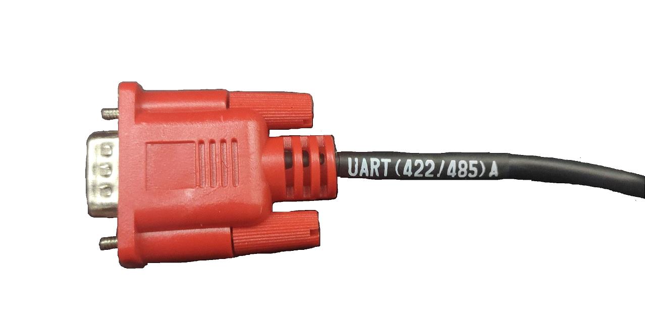
UART (422 / 485) connecting line and pin definition
Apex Xavier II + supports two-way 422 / 485 serial communication, namely UART (422 / 485) a and UART (422 / 485) B. RS422 is full duplex and RS485 is half duplex. The red DB9 terminal is used in the transfer line, as shown in the figure:
|
|---|
Figure UART(422/485) DB9 connector pin assignment |
Pin definition of DB9 terminal of 2 UART (422/485):
Figure UART(422/485) pin numbers |
Note: RS485 only needs to be connected to Pin1, Pin2 and pin5 of DB9 connector. Please refer to the following table for specific wiring sequence
| Interface name | Pin | Signal | node number |
UART(422/485)A | 1 | UART(422T+/485_A) | ttyUART_422_485_A |
| 2 | UART(422T-/485_B) | ||
| 3 | UART(422R+) | ||
| 4 | UART(422R-) | ||
| 5 | GND | ||
UART(422/485)B | 1 | UART(422T+/485_A) | ttyUART_422_485_B |
| 2 | UART(422T-/485_B) | ||
| 3 | UART(422R+) | ||
| 4 | UART(422R-) | ||
| 5 | GND |
UART interface configuration method
Open the corresponding device node under / dev / < device node number >, and set baud rate, stop bit, parity bit, data bit, etc. You can use the stty command to configure the baud rate, stop bit, parity bit, data bit, etc. of the serial port. See the description of the stty command for details.
For the command example, please modify the < > information to the serial port node number to be adjusted. For the specific correspondence, please refer to the [equipment node number] section
sudo stty -F /dev/<UART_XXX> speed 115200 cs8 -parenb -cstopb -echo
输出数据测试
sudo echo “miivii tty debug” > /dev/<UART_XXX>
使用下面命令接收输入数据
sudo cat /dev/<UART_XXX>
Chapter 5: CAN port and function introduction
Can (can FD) connection line and pin definition
Can bus is equipped with can chip, also its equipped with 120 Ω terminal resistance by default
Apex Xavier II + supports 5-channel can bus communication. I/O 1 contains 2 channels, which are can_ A and CAN_ B; I/O 2 contains three channels, which are can_ C,CAN_ D and CAN_ E。 White DB9 terminal is used in the transfer line
|
|---|
Figure physical drawing of can adapter line |

DB9 terminal pin definition of CAN bus:
DB9 terminal pin definition of CAN Bus: |
| CAN_A | CAN_B | CAN_C | CAN_D | CAN_E | ||||||||||
| Pin | Signal | Node | Pin | Signal | Node | Pin | Signal | Node | Pin | Signal | Node | Pin | Signal | Node |
| 2 | CAN_A_L | CAN0 | 2 | CAN_B_L | CAN1 | 2 | CAN_C_L | CAN2 | 2 | CAN_D_L | CAN3 | 2 | CAN_E_L | CAN4 |
| 7 | CAN_A_H | 7 | CAN_B_H | 7 | CAN_C_H | 7 | CAN_D_H | 7 | CAN_E_H | |||||
Can port configuration method
For the specific use method of can equipment, refer to https://github.com/linux-can/can-utils include cansend.C and candump.c
Test command:
sudo modprobe can

sudo modprobe can_raw

sudo modprobe mttcan

sudo ip link set can0 type can bitrate 500000 sjw 4 berr-reporting on loopback off

sudo ip link set up can0

sudo cansend can0 123#abcdabcd

sudo candump can0

sudo ip -details -statistics link show can0

sudo ifconfig can0 down
Can FD configuration usage method10:
sudo modprobe can

sudo modprobe can_raw

sudo modprobe mttcan

sudo ip link set can0 type can bitrate 500000 sjw 4 dbitrate 2000000 dsjw 4 berr-reporting on fd on

sudo ip link set up can0

sudo cansend can0 213##011
10 difference between can FD and can 2.0:
1)
sudo ip link set can0 type can bitrate 500000 dbitrate 2000000 berr-reporting on fd on
Where bitrate is can2 Baud rate in 0 mode; dbitrate is the baud rate in can FD mode. According to the official document, the maximum value can be configured as 5m. 2m is best for general applications;
2)
sudo cansend can0 213##011
In the send command, there is an # between the ID and the data, and the first byte (0) after the ## is canfd_ frame. The value of flags, ranging from 0 to f; canfd_ frame. The byte (11) after flags is the first data, and a maximum of 64 bytes can be transmitted at a time.
Configuration method of extended can FD port
How to use extended can FD configuration: (for product apex2+: can2, can3, can4)
#can2
sudo ip link set can2 up type can bitrate 500000 sjw 4 dbitrate 5000000 dsjw 4 restart-ms 1000 berr-reporting on fd on
sudo ifconfig can2 txqueuelen 65536
#can3
sudo ip link set can3 up type can bitrate 500000 sjw 4 dbitrate 5000000 dsjw 4 restart-ms 1000 berr-reporting on fd on
sudo ifconfig can3 txqueuelen 65536
#can4
sudo ip link set can4 up type can bitrate 500000 sjw 4 dbitrate 5000000 dsjw 4 restart-ms 1000 berr-reporting on fd on
sudo ifconfig can4 txqueuelen 65536
Chapter 6: GPIO port and function introduction
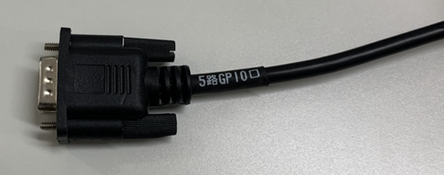
GPIO connector and pin definition
Apex Xavier II + supports 8-channel GPIO port communication, which is led out by 2-channel DB9 terminals, namely "5-channel GPIO port" and "3-channel GPIO port". The black DB9 terminal is used in the transfer line.
如图所示:
|
|---|
Fig. 5 physical drawing of GPIO adapter line |
Definition of DB9 terminal pin of 5 GPIO port:
Figure GPIO_ A pin number diagram |
Interface name | DB9 Pin | Signal definition | Interface Description | pin number |
|---|---|---|---|---|
| GPIO_A | 1 | GPIO_1 | GPIO IN | 339 |
| GPIO_B | 2 | GPIO_13 | GPIO IN | 443 |
| GPIO_C | 3 | GPIO_24_3V3 | GPIO OUT | 387 |
| GPIO_D | 4 | GPIO_26_3V3 | GPIO OUT | 390 |
| GPIO_E | 5 | GPIO_33_3V3 | GPIO OUT | 413 |
| GND | 6-9 | GND | GND |
|
|---|
| Figure GPIO DB9 adapter wiring physical diagram |

Definition of DB9 terminal pin of 3 GPIO port:
Figure GPIO_ B pin number diagram |
Interface name | DB9 Pin | Signal definition | Interface Description | pin number |
|---|---|---|---|---|
| GPIO_F | 3 | GPIO_12 | GPIO IN | 241 |
| GPIO_G | 5 | GPIO_11 | GPIO IN | 240 |
| GPIO_H | 1 | GPIO_7_3V3 | GPIO OUT | 238 |
| GND | 6/8 | GND | GND |
GPIO interface configuration method
The example of GPIO interface is as follows. Please modify the < > information to the GPIO node number to be adjusted. For the specific correspondence, please refer to the [pin number] section
# switch to root user
sudo su -
# Set to high (DO)
echo 1 > /sys/class/gpio/<gpio339>/value
# Set to low (DO)
echo 0 > /sys/class/gpio/<gpio339>/value
# read data (DI)
cat /sys/class/gpio/<gpio339>/value
If you need to preserve the configuration after shutdown, you can write the above command to / etc / RC Local file
Device GPIO output mode description
| Do output mode | Mode description |
|---|---|
| Push pull output | The internal load resistance can stabilize the output level signal. At high level, do pin stably outputs 3.3V voltage; at low level, do pin outputs 0V. The maximum supporting current of push-pull output is 10mA. |
Chapter 7: extended equipment configuration method
M. 2 SSD hard disk
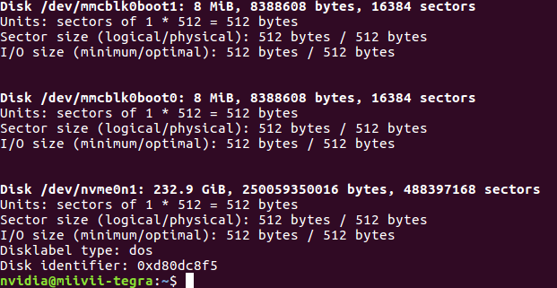
check ssd information:
sudo fdisk -lu
|
|---|
Figure screenshot of viewing hard disk information page |
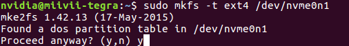
Format hard disk:
sudo mkfs -t ext4 /dev/nvme0n1
|
|---|
Figure screenshot of formatted hard disk |
View hard disk UUID:
sudo blkid /dev/nvme0n1
|
|---|
Figure screenshot of hard disk UUID |

Setting method of automatic mounting SSD: Create a systemd service in the /etc/systemd/system path to automatically mount the SSD when booting, such as: miivii_mount_ssd.service
#vim miivii_mount_ssd.service   Create service miivii_mount_ssd.service
[Unit]
Description=MIIVII specific script
After=udev.service

[Service]
ExecStart=/etc/systemd/miivii_mount_ssd.sh

[Install]
WantedBy=multi-user.target
Create a script under the path of / etc / SYSTEMd / to mount the hard disk, such as miivii_ mount_ ssd. sh
#vim miivii_mount_ssd.sh   Create a service script miivii_mount_ssd.sh
#!/bin/bash
mount -o rw /dev/nvme0n1 /home/nvidia/workspace
change mode for this script
sudo chmod +x miivii_mount_ssd.sh
Set the mounted SSD service to start at boot
sudo systemctl enable miivii_mount_ssd.service
WiFi Setting
MIIVII apex Xavier II + is provided by the mini-pcie external expansion module. If you need to use this function, please ensure that the WiFi module is selected when purchasing the machine.
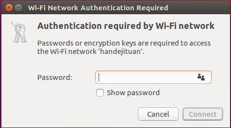
Please find the WiFi name to be connected in the network connection icon in the upper right corner of the Ubuntu system desktop and click, then enter the password in the pop-up password box and click Connect.
|
|---|
| Figure screenshot of WiFi connection |
4G Module Configuration Method
The 4G function of apex Xavier II + is provided by the mini-pcie external expansion module. If you need to use this function, please ensure that the 4G module is selected when purchasing the machine.
Please note that if you use an IOT SIM card, there will be a problem of binding the SIM card to the device hardware. Please confirm with the SIM card supplier in advance.
In the system image, the corresponding 4G module driver is integrated. After installing the 4G module, the system will automatically identify it. Check the / dev directory and you will see / dev / ttyusb0 ~ / dev / ttyusb3, total of four devices.
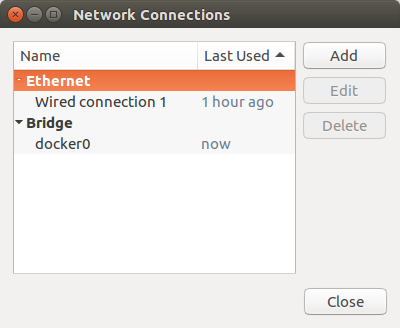
In the network connection icon on the top right of the desktop, find edit connections and click add, as shown in the figure:
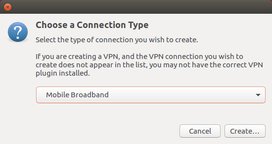
Select the connection type mobile broadband
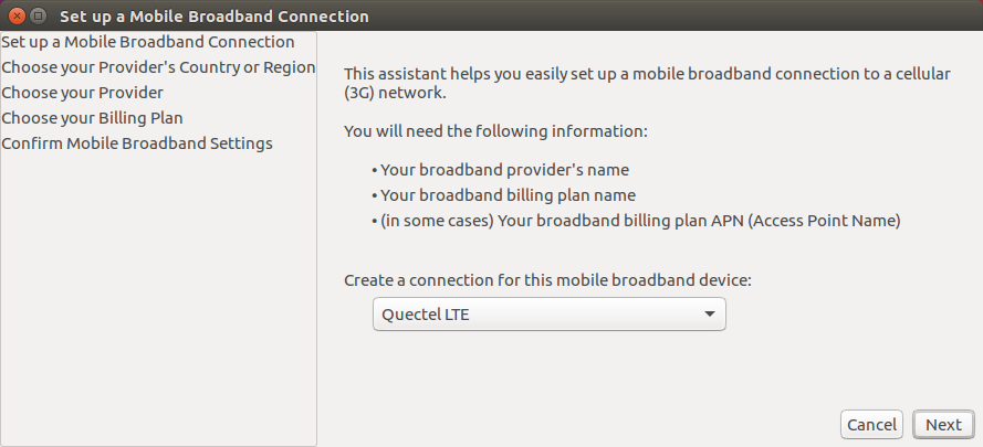
Select next (options quectel LTE, fibocom nl668 modem, Android and any device etc. display different information according to different models of 4G modules. You can click Next directly)
Select the country as your country, then choose network provider.
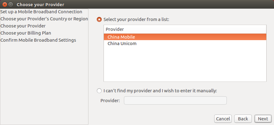
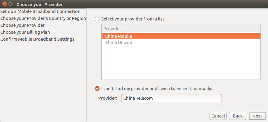
If the operator is China Telecom, then create the operator manually
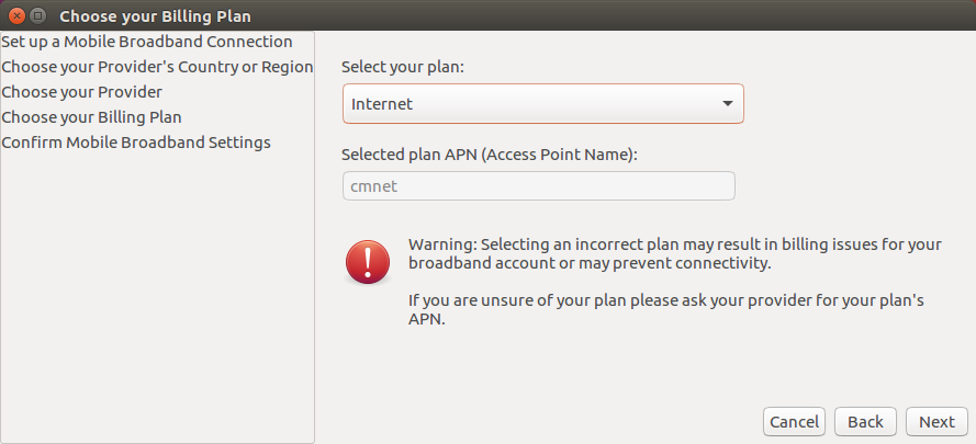
Choose your Plan
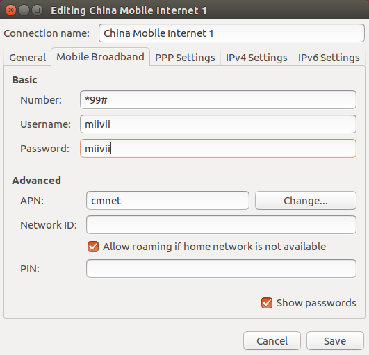
China Mobile choose 'Internet',China Unicom and China Telecom choose default
APN settings: China Mobile: cmnet; China Unicom: 3gnet; China Telecom: ctnet
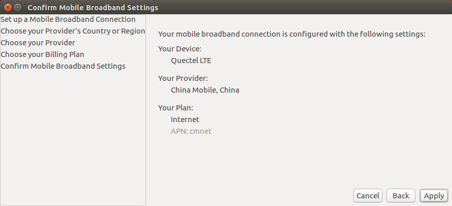
Check the created information. If all correct, click apply
Set username and password,click save
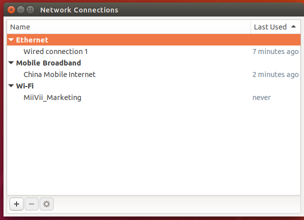
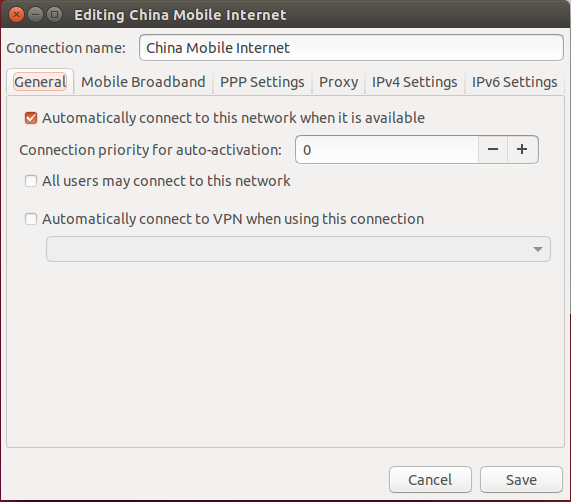
After the network is created, select the new connection in the network connection icon at the top right of the desktop to access the Internet . If 4G automatic connection is required at startup, take mobile as an example, after establishing the connection file “China Mobile Internet”, the operation is as follows: click the network connection icon at the top of the desktop and click the edit connections option in the drop-down menu. Select the China Mobile Internet option in the pop-up window and click the settings Icon below
Select 'General', then check 'Automatically connect to this network when it is available'
Reset MiiVii device, you can automatically connect to 4G network
Appendix 1
Apex Xavier II+ General usage
system introduction
Miwen devices use Ubuntu 1804 system. Default username: nvidia; password: nvidia
Turn On/Off machine
Boot: The default boot mode of Miivii device is power-on auto-start. Plug in the power supply, and connect the monitor to the Miivii device through the HDMI interface. The startup screen is as shown in the figure:
|
|---|
| Figure Desktop Screen |

Power off: long press the POWER_ONKEY button to power off. Or execute sudo poweroff in the command line to complete the soft shutdown. Reboot: execute sudo reboot in the command line to complete the restart
Power Mode Settings
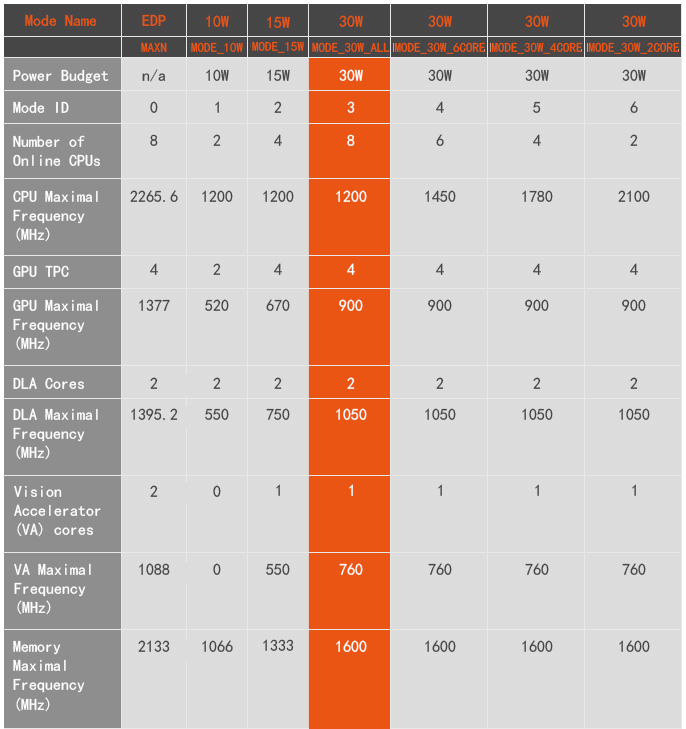
Miivii devices equipped with Jetson AGX Xavier have multiple working modes. This can be adjusted via the NVIDIA green logo setting in the upper right corner. The default mode for Miivii devices is 3: MODE_30W_ALL
|
|---|
| Figure Settings Icon |

Click the drop-down menu to modify the working mode of the Miivii device. The details of the working mode are shown in the following table:
You can also use command line adjustments:
#View the current mode of the device
sudo nvpmodel -q verbose
# set to a mode
sudo nvpmodel -m <MODE ID>
#Get the best performance in the current mode
sudo jetson_clocks
#check the detail information
sudo jetson_clocks --show
Application function usage
Miivii equipment provides a variety of samples, which is convenient for customers to develop and quickly verify
MiiVii Dynamics also provides some open source code for developers, please check it on MiiViiDynamics Github https://github.com/MiiViiDynamics
Exception handling
buzzer
buzzer | One short beep: After power on, the power supply is normal One long beep: the system is in flash mode Looping five short beeps: System startup failed |
If there is an abnormal situation during the development process, you can first print the log through the DEBUG serial port to judge the problem by yourself. The specific operations are as follows:
Step 1: Find the specific location of the DEBUG interface according to the information in the [Interface Description] section
Step 2: Use an RS232-USB adapter cable to connect the DEBUG interface to the upper computer PC
Step 3: On the PC side of the host computer, download the serial debugging tool and adjust the baud rate to 115200 Baud
Step 4: Grab the serial port log in the serial port debugging tool to analyze abnormal problems
Appendix 2
Jetpack 4.5 and Above Image Burning
1.Function Introduction
Miivii flash tool, suitable for Miivii series products.
Miivii flash tool is a tool software provided for the convenience of burning, writing, cloning and small batch production of Miivii equipment.
You can burn the Miivii official image to Miivii equipment by using X86 architecture PC as the burning host. After a period of development of Miivii equipment, the existing equipment can be mirrored and cloned to save the development progress, and burned to other Miivii equipment in a single or small batch of products.
Core Function
- Automatic detection of useing environment
- Automatically detect the latest mirror
- Build-in image downloader, no need to download images manually.
- Support batch burning
- Support mirror cloning(It should be noted that you need to use the same Jetpack version before burning after Clone.)
2.Prepare Software and Hardware
2.1. Burning Host Preparation
You need to connect the burning host with the Miivii device to burn the image. The recommended configuration of the burning host is as follows:
● Intel Core ™ series processors with CPU X86/X64 architecture, at least 4 cores.
●Memory 8GB ddr3 and above,DDR3/DDR4/DDR5
● The disk format of the burning host is recommended as EXT4.
● Spare hard disk capacity 40G and above
● The system is Ubuntu Linux x64 v16.04 , v18.04 or v20.04 ( As of v1.6.0.8 , support Ubuntu20.04, "sudo apt-get install miivii-ftool " Upgrad version & View version )
2.2. Burning Software Environment Preparation
● sudo apt install python2.7 python3 python
2.3. Prepare Miivii Burning Tool and Miivii Equipment Image.
2.3.1.Burning Tool Installation
- Prepare PC host,System is:Ubuntu Linux x64 v16.04 , v18.04 or v20.04 ( As of v1.6.0.8 , support Ubuntu20.04, "sudo apt-get install miivii-ftool " Upgrad version & View version )
Install key
sudo apt-key adv --keyserver keyserver.ubuntu.com --recv-keys 05BE38FE8ADA7CD12E3281B52FC7A8453C3B8F24
Add a source to the local ubuntu system
sudo sh -c 'echo "deb http://upgrade.miivii.com/miiviitools/ mvtools main" > /etc/apt/sources.list.d/miivii-l4t-apt-source.list'
Manual update
sudo apt update
apt-get install 、brush tool 、Deb bag
sudo apt-get install miivii-ftool
- After installation (click “Show Applications” in 18.04 system or “Search Your Computer” in 16.04 system), you will find the following shortcuts

- Double-click shortcut,enter password:Your sudo password。
2.4. Prepare Hardware
● Miivii device and power supply, USB data cable
3.Operate
3.1. Hardware Connection
- Connect the burning interface of Miivii device with the burning host through USB data line;
- Press and hold the RECOVERY button of the Miivii device, and then power on the Miivii device to enter the FORCE_Recovery burning mode.
3.2 Software Trial
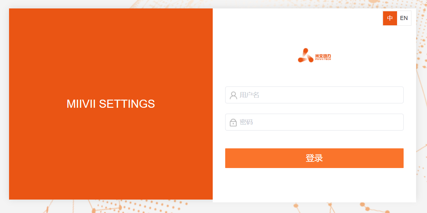
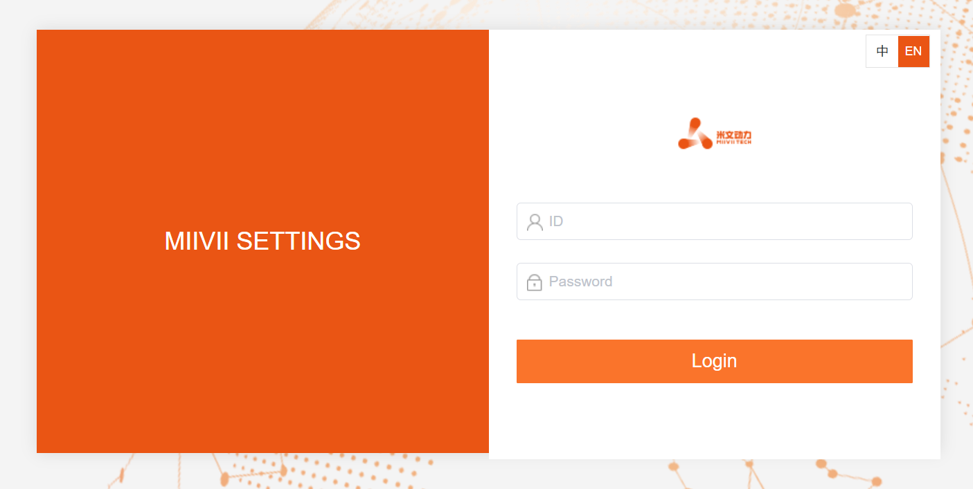
Select English at the top right of the login page.
Input host user name and password.
3.2.1. Mirror Burning
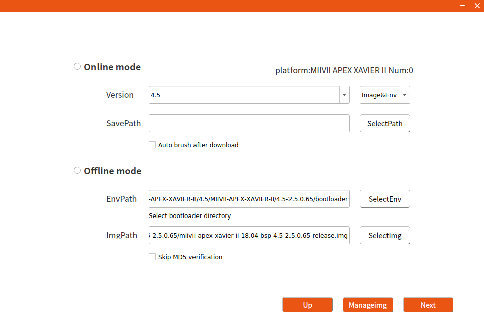
3.2.1.1 On-line Mode Mirror Burning
- Click the "Online mode" checkbox, select Jetpack version and download path, then click "Next" to start downloading the latest brush environment and device image of the selected version.
- Choose whether to start brushing automatically after the download is completed. If you choose Auto, decompression, verification and brushing will be performed automatically after the download is completed.
- The download speed depends on the network speed of the environment, generally up to 5M/s.
- It usually takes more than 15 minutes to finish . Please be patient.
3.2.1.2 Off-line Mode Mirror Burning
- Click the "Offline mode" checkbox, select the downloaded brush environment and device image, and click "Next" to start burning directly.
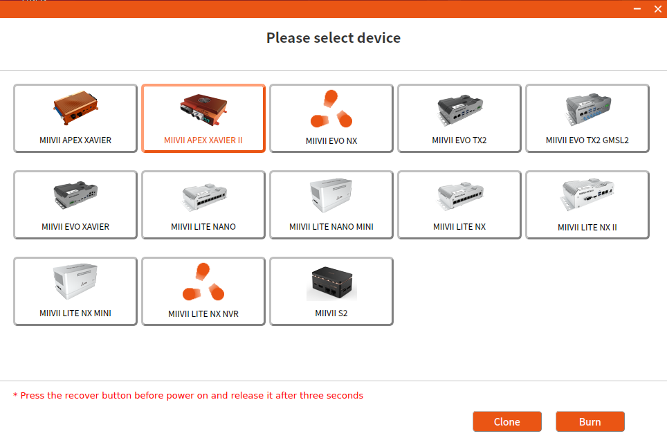
3.2.2. Mirror Clone
- Enter the Miivii device into FORCE_Recovery mode according to the method of 3.1, and open the burning tool.
- Click the "Enter password" button ,enter the boot password of the burning host.
- Click "Clone" button,enter cloning operation.
- Modify the path and name of the cloned file stored in the burning host, and click "Clone".
Note: Chinese or special characters are not allowed in the file storage path.
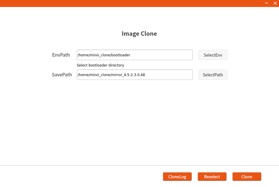
- Cloning usually takes more than 30 minutes to complete:
- After the clone is completed, the clone image and MD5 file will be generated. Please follow the steps in 3.2.1 to burn again.
Note: If you have any problems in the process of image burning and cloning, please contact Miivii after-sales mailbox for help: helpdesk@miivii.com.
Appendix 1. Self-check of Burning Problem
If you have any burning problems, please check yourself according to the following items first:
- Whether the PC boot password is entered in the upper left corner of the burning tool.
- Whether you have entered Recovery mode, which can be identified by lsusb command.
- Whether the quality of Micro USB and dual Type A cables is up to standard, and whether they are for charging.
- Whether the upper computer is a desktop or notebook computer with X86-64 architecture. (Currently, other devices such as servers, embedded devices and virtual machines are not supported)
- Whether the host computer system is Ubuntu Linux x64 v16.04 , v18.04 or v20.04 ( As of v1.6.0.8 , support Ubuntu20.04, "sudo apt-get install miivii-ftool " Upgrad version & View version )
- Check the disk format, the disk format of the burning host is recommended as EXT4.
- Whether the upper computer capacity is sufficient.
- The mirror burning tool storage path cannot contain Chinese characters or other special characters.
Appendix 2. Flash Tools Release Note
Product | Date | Version | Update content | Remark |
|---|---|---|---|---|
| MiiVii-FTool | 2022/08/16 | V1.6.0.8 | Add:MIIVII LITE TX2 NX II Add:MIIVII LITE TX2 NX MINI Add:MIIVII APEX AD10 Add:Supports Ubuntu20.04 Host OS Add:Add prompts of " The mirror clone supports only EMMC " Fixed: Less than 60 GB is displayed when the free disk space is greater than 2 TB | |
| MiiVii-FTool | 2022/06/29 | V1.5.0.2 |
| |
MiiVii-FTool | 2022/06/14 | V1.4.0.119 | Function Update:
| To ensure compatibility, the OS version will be checked when the software is started. V1.4.0.119 also supports only Ubuntu16.04 and Ubuntu18.04. Future versions will support more operating system versions. |
Instructions for using online system upgrade (OTA)
Summary
Online system upgrade, usually called OTA, is a software service provided by MIIVII for all MIIVII devices.
That is, the system firmware can be updated without brushing.
Starting from Jetpack 4.5, all MIIVII devices support OTA.
Usage Mode
Method 1 (recommended): use MIIVII SETTINGS for version upgrade and rollback;
- Open the browser on the device and enter http://127.0.0.1:3000, or enter http://<device ip>:3000 on the remote PC browser.
- Use the system login account to log in to the MIIVII SETTINGS;
- Select the system upgrade function and click "检查更新" to check whether there is a new version.
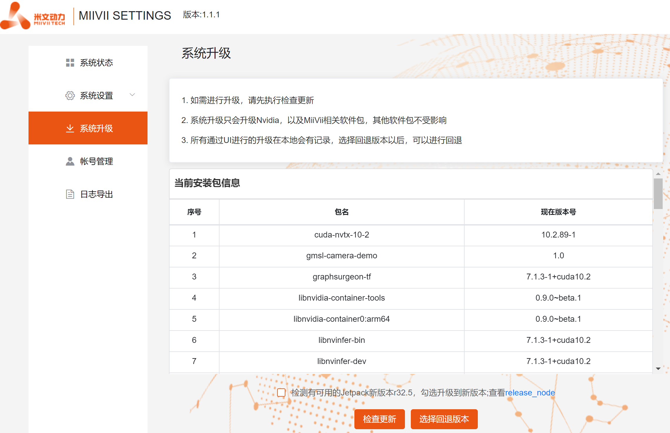
- When an upgraded version is detected, you can click "系统升级" to upgrade the installation package.
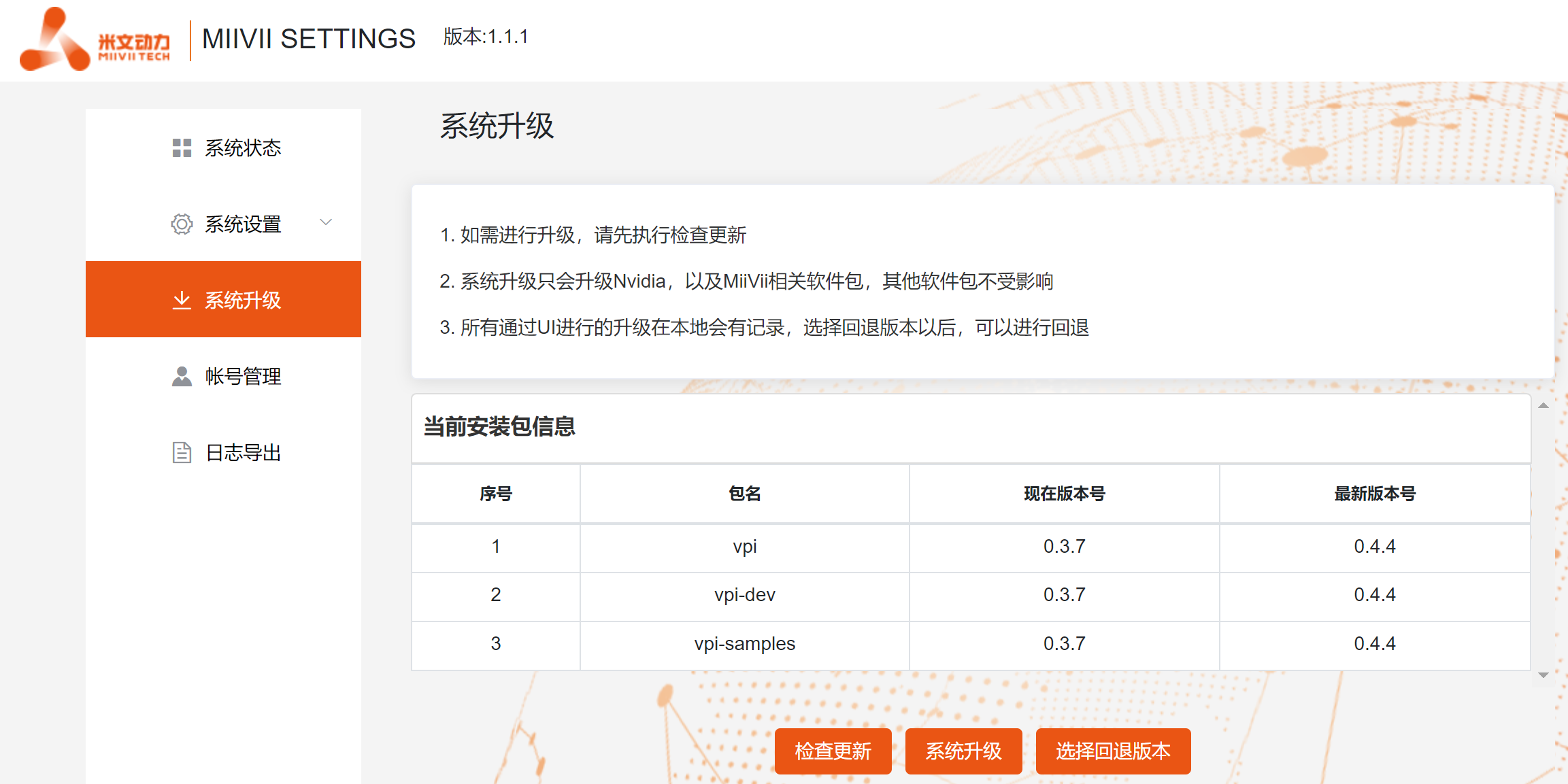
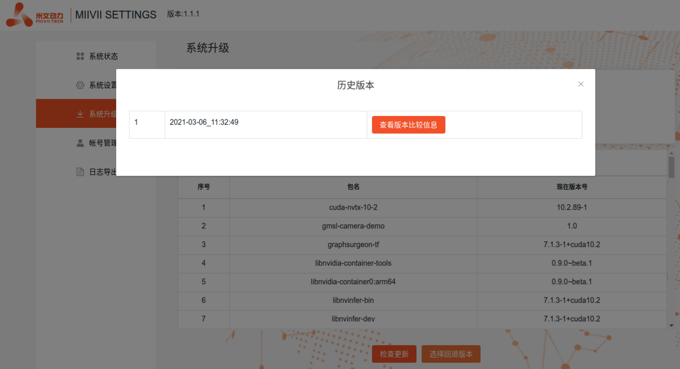
- After the upgrade is completed, the system will record the upgrade time, and you can view the upgrade record of that time.
- Restart the system after the upgrade to ensure that the upgrade takes effect.
Method 2: Use the command line to upgrade or upgrade the specified installation package.
Specify The Upgrade Installation Package
Execute the following command to update the source.
sudo apt update
Execute the following command to upgrade the specified installation package.(Take updating websettings 1.4.0 as an example.)
sudo apt install -y miivii-websettings=1.4.0
2.Upgrade All (Including Ubuntu package upgrade, please choose carefully)
Execute the following command to update the source.
sudo apt update
Execute the following command to upgrade the system.
sudo apt upgrade -y
Restart the system after the upgrade to ensure that the upgrade takes effect.
Appendix 3
MIIVII WEB SETTINGS Manual(JP 4.5 or later)
Introduction
MIIVII WEB SETTINGS is a graphical tool based on web,for device settings .
Provides such functions as system status detection, remote access, remote login and so on.
Access Method:
Method1- Access shortcut on local desktop:
- Double-click the desktop shortcut of “MIIVII WEBSETINGS” ,open the application of MIIVII WEBSETINGS
The login user must have root permission . The user without root permission cannot use it .
Default ID : nvidia Default PWD: nvidia
Method2- Access local browser:
- Open local browser
- Input http://127.0.0.1:3000
The login user must have root permission . The user without root permission cannot use it .
Default ID : nvidia Default PWD: nvidia
Method3- Access browser of client PC in same LAN:
- Open browser of client PC in same LAN
- Input “ The LAN IP of device + port number”,port number is 3000 . For example http://192.168.1.100:3000
The login user must have root permission . The user without root permission cannot use it .
Default ID : nvidia Default PWD: nvidia
Function Description
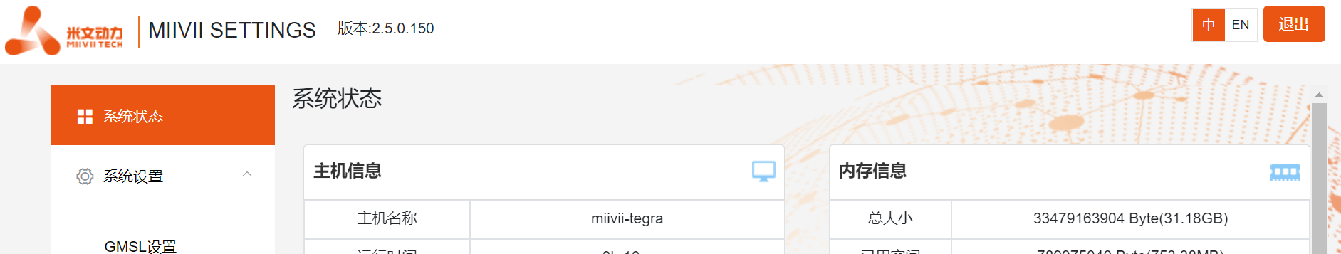
Switching between Chinese and English interface
In the upper right corner of the page ,click the switch button  , The interface can be switched between Chinese and English .
(Chinese/English switching is available from MWS V2.5.x and later versions)
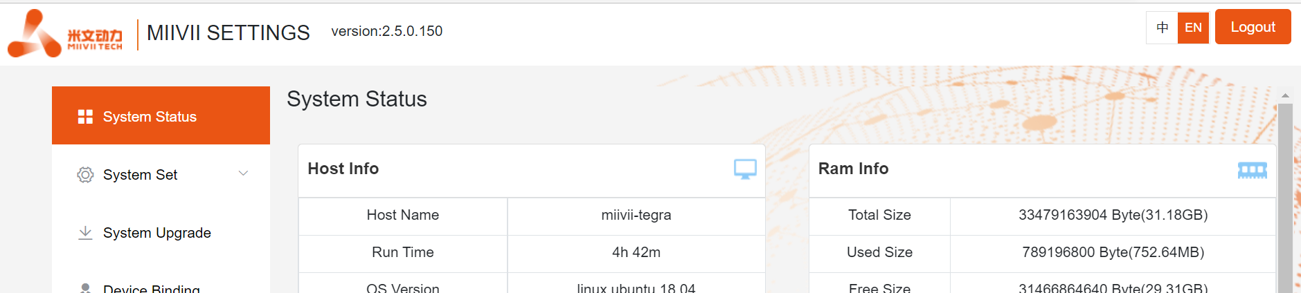
System Status
View basic information about the current system, such as CPU usage, memory usage, and storage usage.
- Click "System Status" on the left menu bar to enter the page.
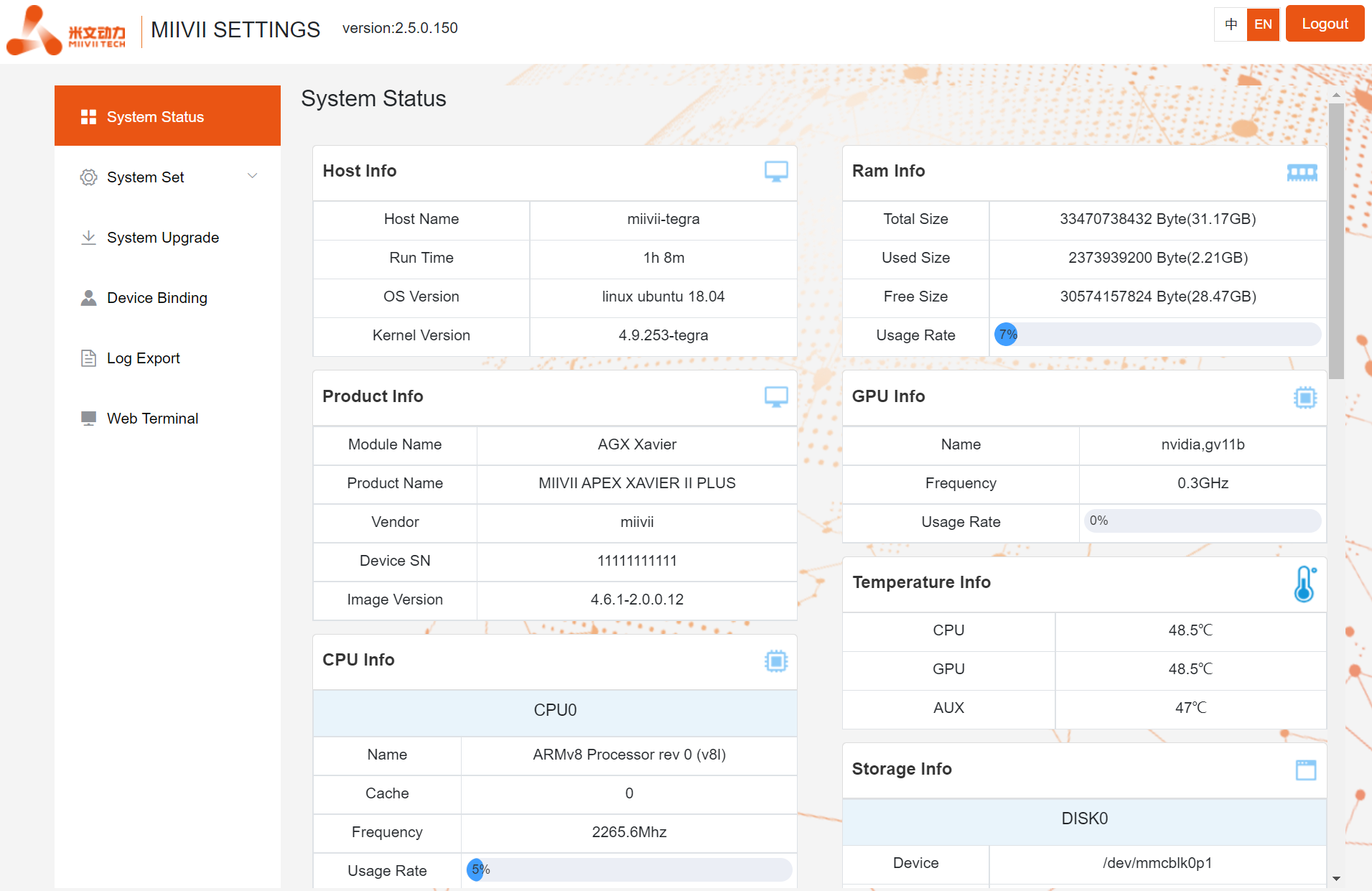
You can also view the system version on the CLI(For LAN access, use the "WEB Terminal" function):
cat /etc/miivii_release
APEX 4.2.2-1.5.0
System Settings
Set up basic system functions, such as system timing Settings, GMSL camera Settings and so on.
GMSL Settings
- Click the left menu bar "System Settings -GMSL Settings" to enter the page.
- Select the camera model for each channel
- Click “Save” Button
- After a while, the system will indicate that GMSL is set up successfully, and you can use the GMSL camera.
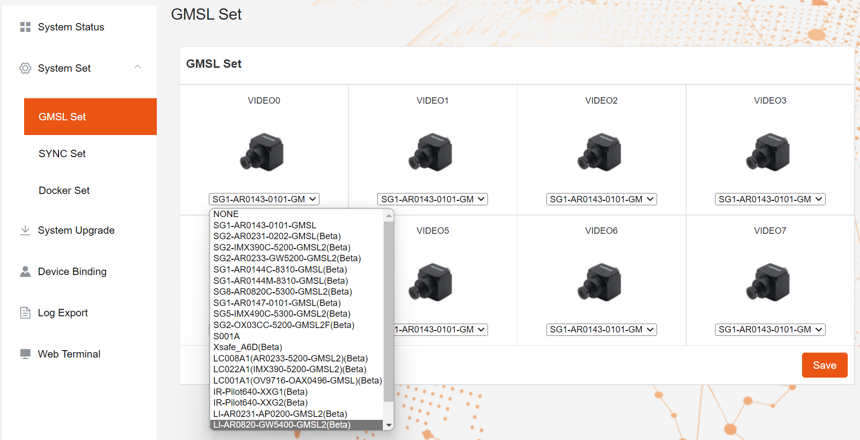
- The Apex has two GMSL1 camera interfaces, named GMSL_A and GMSL_B .
- The Apex Xavier II has 8 GMSL2(Compatible with GMSL1)camera interfaces,named GMSL_0-7
- The Apex Xavier II+ has 8 GMSL2(Compatible with GMSL1)camera interfaces,named GMSL_0-7
- The EVO TX2 GMSL2 has 6 GMSL2(Compatible with GMSL1)camera interfaces,named GMSL_0-5
- EVO Xavier, EVO Xavier II,EVO TX2 and S2 don't have the function of GMSL/GMSL2 camera
Configuration file path:
/opt/miivii/config/gmsl_camera/camera.cfg
- Camera configuration ID please refer to "GMSL Camera Support List".
- Manually modifying a configuration file takes effect only after the system restarts.
Sync Settings (system timing Settings)
Click the left menu bar "System Set - SYCN Set" to enter the page.
Choose external timing mode : NTP/GPS/NONE
- "NTP" is the default mode. NTP network timing mode:
- The device is connected to the network and timed by the NTP service. The device can be used as a synchronous source to time and synchronize the sensor.
- "GPS" is GPS external timing mode.:
- In this case, the device is connected to GPS and timed by GPS. The device can be used as a synchronization source to time and synchronize the sensor
- "None" is the asynchronous mode. In this case, the device is not timed but can be used as the synchronization source.
- "NTP" is the default mode. NTP network timing mode:
Set Sync out :
- Adjust the Sync out output frequency. Note that this is not the GMSL frequency.
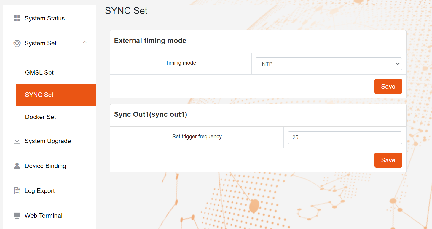
- "Apex Xavier", "Apex Xavier II", "Apex Xavier II+" have the function of SYNC
- "EVO Xavier", "EVO Xavier II", "EVO TX2 GMSL2", "S2Pro" have the function of SYNC
- "EVO TX2" , "S2" don't have the function of SYNC
- "LIte xxxx" product series don't have the function of SYNC
Configuration file path:
/opt/miivii/config/sync/sync.cfg
- The timing mode is implemented by modifying the X value of "sync_type:X".
- 0: GPS external timing mode
- 1: NTP network timing mode
- 2: Asynchronous mode
cat /opt/miivii/config/sync/sync.cfg
sync_out_freq:25
sync_type:2
/*
note:
sync_out_freq---the frequency is 25 for sync out time
sync_type---0 is for GPS calibrate time
1 is for SYS calibrate time
2 can not calibrate time
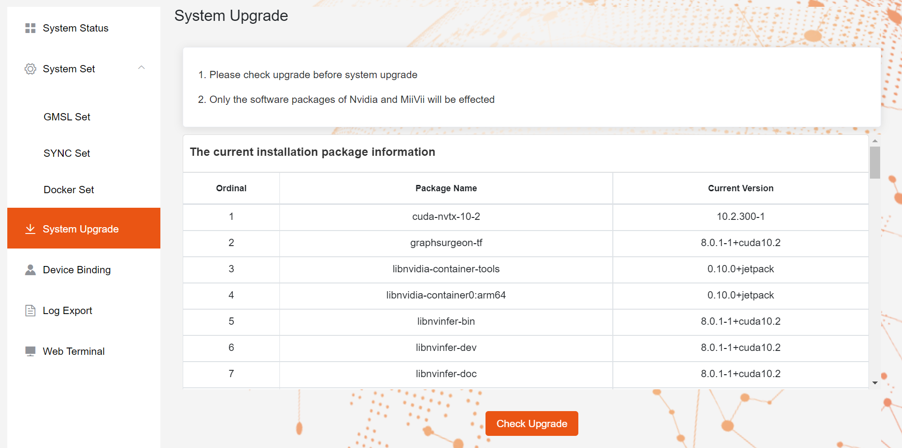
System Upgrade
MiiVii provides OTA upgrades to equipment systems.
Click the left menu bar "System Upgrade" to enter the page.
- Click "Check Upgrade" , If have new version , click ""
Device Binding
MiiVii provides the EdgeService cloud service. Enabling the cloud service requires binding devices.
Click the left menu bar "Device Binding" to enter the page.
- Bind the device as prompted. Use wechat to scan.

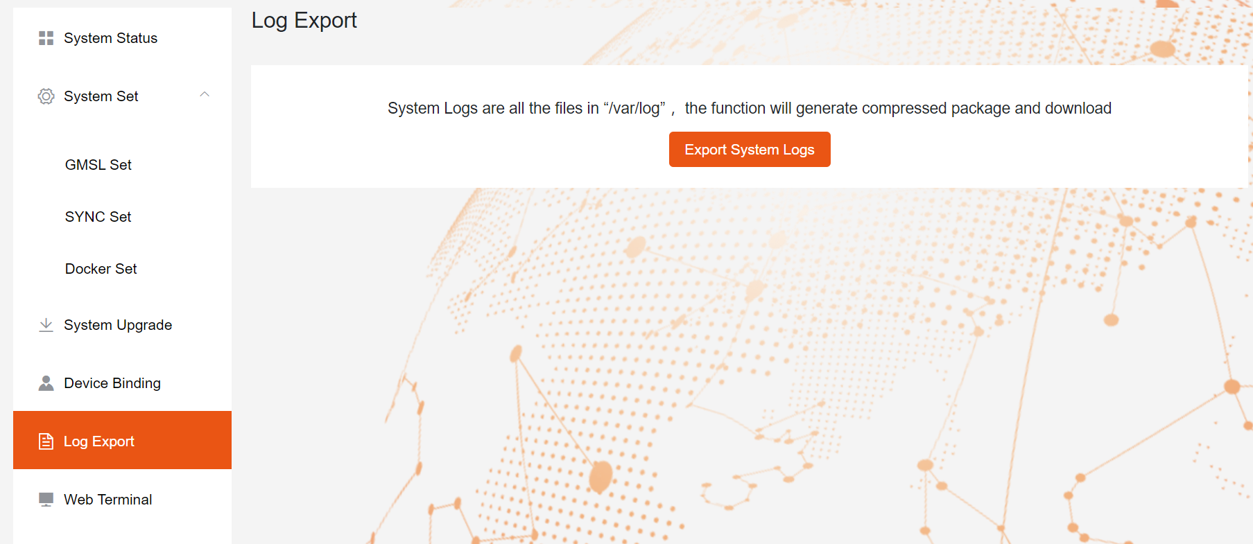
The log export
System run logs are stored in logs in /var/log/,The Log Export function allows you to package and download logs to a local PC.
Click the left menu bar "Log Export" to enter the page.
- Click "Export System Logs" to complete.
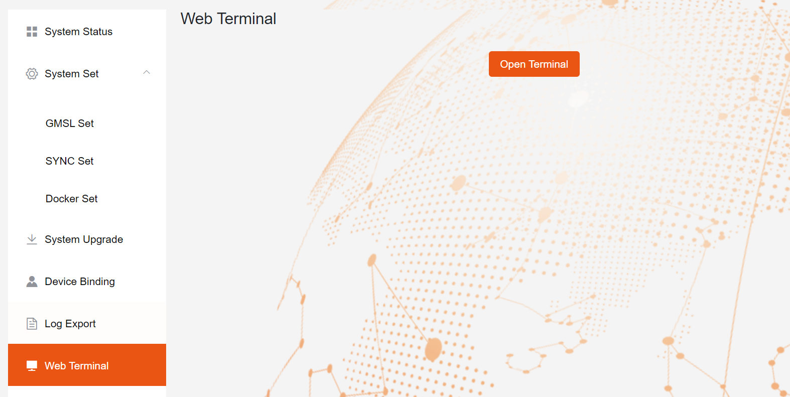
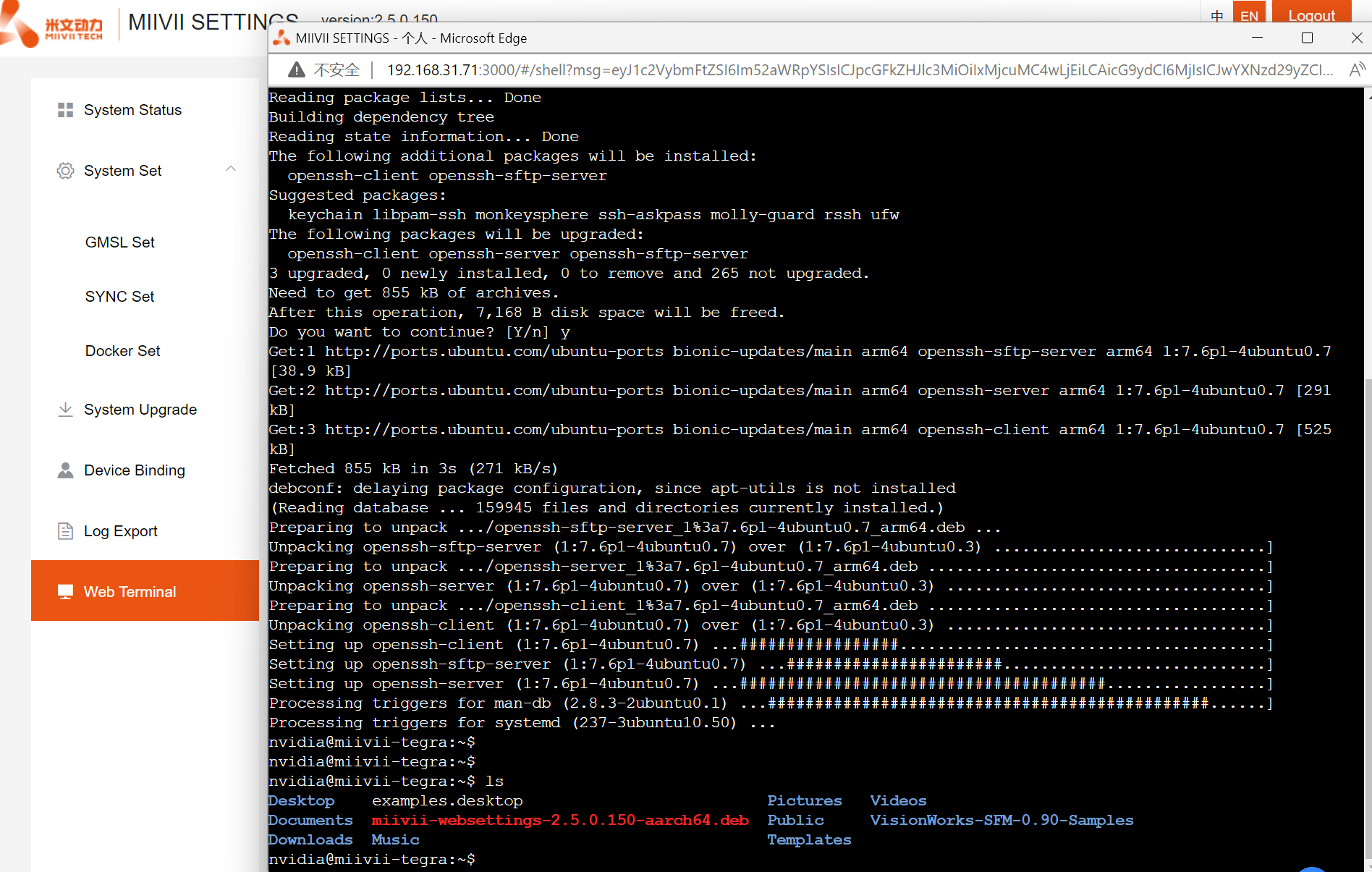
WEB Terminal
MiiVii Web Settings provides the remote terminal function through the WEB
Click "WEB Terminal" on the left menu bar to enter the page.
Click "Open terminal" to open the WEB terminal (as shown below)
Appendix 4
Extended Device Support Checklist
序号 NO. 品牌 Brand 产品型号 P/N 相机ID Camera ID 支持类型 Type of support 快门类型 shutter type 分辨率 Resolution 帧率 FPS SG5-IMX490C-5300-GMSL2 注: 正式支持:每次米文系统版本升级,会在米文设备上进行验证。 BETA支持:米文调试过,但不会在每次米文系统版本升级中验证,如使用过程中需要进一步支持请联系对应的销售工程师或客户经理。 Note: Official support: Every time the Miivii system version is upgraded, it will be verified on the Miivii device.GMSL摄像头支持
GMSL Camera Support List
1 Leopard LI-AR0233-NVP2650-GMSL2 MVG2CB-006D Beta Rolling 1920*1080 30 FPS 2 Leopard LI-AR0231-AP0200-GMSL2 MVG2CB-006A Beta Rolling 1920*1020 5~28.7 FPS 3 Leopard LI-IMX490-GW5400-GMSL2 MVG2CB-006C Beta Rolling 2880*1860 25 FPS 4 Leopard LI-AR0820-GW5400-GMSL2 MVG2CB-006B Beta Rolling 3840*2160 15 FPS 5 Leopard LI-ISX031-GMSL2 MVG2CB-006F Beta Rolling 1920*1536 5~30fps 6 Sensing SG1-AR0143-0101-GMSL MVG2CB-001A 正式/Official Rolling 1280*720 30 FPS 7 Sensing SG1-AR0147-0101-GMSL MVG2CB-001H Beta Rolling 1280*720 30 FPS 8 Sensing SG1-AR0144C-8310-GMSL MVG2CB-001E Beta Global 1280*720 30 FPS 9 Sensing SG1-AR0144M-8310-GMSL MVG2CB-001F Beta Global 1280*720 30 FPS 10 Sensing SG2-AR0231-0202-GMSL MVG2CB-001B Beta Rolling 1920*1080 22 FPS 11 Sensing SG2-AR0233-GW5200-GMSL2 MVG2CB-001D Beta Rolling 1920*1080 30-60 FPS 12 Sensing SG2-IMX390C-5200-GMSL2 MVG2CB-001C Beta Rolling 1920*1080 30 FPS 13 Sensing SG2-OX03CC-5200-GMSL2F MVG2CB-001J Beta Rolling 1920*1080 30fps 14 Sensing SG3-ISX031C-GMSL2 MVG2CB-001L Beta Rolling 1920*1536 5~30fps 15 Sensing MVG2CB-001I Beta Rolling 2880*1860 30 FPS 16 Sensing SG8-AR0820C-5300-GMSL2 MVG2CB-001G Beta Rolling 3840*2160 30 FPS 17 丽景 LC008A1(AR0233-5200-GMSL2) MVG2CB-004A Beta Rolling 1920*1080 30 FPS 18 丽景 LC001A1 (OV9716-OAX0496-GMSL) MVG2CB-004C Beta Rolling 1280*720 30 FPS 19 丽景 LC022A1 (IMX390-5200-GMSL2) MVG2CB-004B Beta Rolling 1920*1080 30 FPS 20 Entron S001A MVG2CB-002A 正式/Official Rolling 1280*720 30 FPS 21 英睿 Xtherm Xsafe_A6D MVG2CB-003A Beta IR 640*512 25 FPS 22 艾睿 InfiRay IR-Pilot640-XXG1 MVG2CB-005A Beta IR 640*512 50 FPS/25 FPS 23 艾睿 InfiRay IR-Pilot640-XXG2 MVG2CB-005B Beta IR 640*512 50fps 24 艾睿 InfiRay IR-Pilot180P MVG2CB-005C Beta IR 1280*720 25 FPS
BETA support: Miivii has added the product driver, but not verified in each Miivii system version upgrade. If you need further support during use, please contact the corresponding sales engineer or account manager.
Mini PCIe 4G支持清单
Mini PCIe 4G Support List
序号 NO. | 品牌 Brand | 产品型号 Product NO. | 支持方式 Support | 使用接口 Interface | 模块功能 Module function | 工作温度 Operating temperature | 规格 Spec | 备注 Note |
|---|---|---|---|---|---|---|---|---|
| 1 | 移远 Quectel | EC20-CEHCLG-MINIPCIE-CB | 正式 Formal | Mini PCIe | 4G | -40ºC - 80ºC | 全网通 Speed: Max 130Mbps (Download)/Max 30Mbps (Upload) | |
| 2 | 移远 Quectel | EC20-CEHC-MINIPCIE-CB | Beta | Mini PCIe | 4G | -40ºC - 80ºC | 全网通 Speed: Max 130Mbps (Download)/Max 30Mbps (Upload) | |
| 3 | 移远 Quectel | EC20-CEHCLG-MINIPCIE-C | Beta | Mini PCIe | 4G | -40ºC - 80ºC | 全网通 Speed: Max 130Mbps (Download)/Max 30Mbps (Upload) |
注:
- 正式支持:每次米文系统版本升级,会在米文设备上进行验证。
- BETA支持:米文调试过,但不会在每次米文系统版本升级中验证,如使用过程中需要进一步支持请联系对应的销售工程师或客户经理。
Note:
Official support: Every time the Miivii system version is upgraded, it will be verified on the Miivii device.
BETA support: Miivii has added the product driver, but not verified in each Miivii system version upgrade. If you need further support during use, please contact the corresponding sales engineer or account manager.
Mini-PCIe WIFI支持清单
Mini-PCIe WIFI Support List
序号 NO. | 品牌 Brand | 产品型号 Product NO. | 支持方式 Support | 使用接口 Interface | 模块功能 Module function | 工作温度 Operating temperature | 无线标准 Standard | 规格 Spec | 备注 Note |
|---|---|---|---|---|---|---|---|---|---|
| 1 | Complex | WLE900VX | 正式 Formal | Mini PCIe | WIFI | -20ºC - 70ºC | Wifi802.11ac | WIFI rate ≤1300Mbps | |
| 2 | Azurewave(海华) | AW-CB161H | 正式 Formal | Mini PCIe | WIFI+BT | 0ºC - 70ºC | Wifi 802.11a/b/g/n/ac BT:4.0 | WIFI rate ≤433.3Mbps |
注:
- 正式支持:每次米文系统版本升级,会在米文设备上进行验证。
- BETA支持:米文调试过,但不会在每次米文系统版本升级中验证,如使用过程中需要进一步支持请联系对应的销售工程师或客户经理。
Note:
Official support: Every time the Miivii system version is upgraded, it will be verified on the Miivii device.
BETA support: Miivii has added the product driver, but not verified in each Miivii system version upgrade. If you need further support during use, please contact the corresponding sales engineer or account manager.
Appendix 5
Apex Xavier II+ Release Note
| Product | Update time | System Version | Update Information | Note |
|---|---|---|---|---|
| MIIVII Apex Xavier II+ | 2022/04/20 | JP4.6.1-2.0.0.12 |
| |
| MIIVII Apex Xavier II+ | 2022/05/15 | JP 4.5-1.1.0.7 |
|